


23015-3-0707 Page 11
VENTING AND INSTALLATION
Vent System Approvals
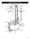
Figure 8 shows the vent termination caps and systems approved
for use with these models. Approved vent system terminations
are labeled for identification. 3-inch diameter listed flexible
aluminum or stainless steel gas vent is used for both the incoming
combustion air and exhaust vent pipes. NO OTHER VENTING
SYSTEMS OR COMPONENTS MAY BE USED. Detailed
installation instructions are included with each vent termination
kit and should be used in conjunction with this manual.
Horizontal Venting
The vent system on this model CANNOT be terminated
horizontally.
Vertical Venting
The inlet and exhaust vent pipes MUST be connected to the
proper collars on the unit
AND to the termination cap or the unit
will not operate. The intake vent collar is identified by a stamped
“I” on the top collar sliding vent plate assembly.
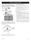
WARNING: MAJOR U.S. BUILDING CODES SPECIFY
MINIMUM CHIMNEY AND/OR VENT HEIGHT
ABOVE THE ROOF TOP. THESE MINIMUM HEIGHTS
ARE NECESSARY IN THE INTEREST OF SAFETY.
SEE FIGURES 8 THROUGH 10 FOR MINIMUM
HEIGHTS, PROVIDED THE TERMINATION CAP IS
AT LEAST 2-FEET FROM A VERTICAL WALL AND
2-FEET BELOW A HORIZONTAL OVERHANG.
Note: This also pertains to vertical vent systems installed on the
outside of the building.
WARNING: THE EXHAUST PIPE MUST ONLY
BE CONNECTED TO THE EXHAUST STARTING
COLLAR OF THE UNIT AND TO THE EXHAUST
COLLAR OF THE TERMINATION CAP.
THE INLET AIR PIPE MUST ONLY BE CONNECTED
TO THE INLET AIR STARTING COLLAR OF THE
UNIT AND TO THE INLET AIR COLLAR OF THE
TERMINATION CAP. BOTH THE INLET VENT AND
THE FLUE VENT MUST BE CONNECTED FROM
THE INSERT TO THE VENT TERMINATION CAP.
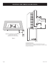
NOTE: The minimum vertical vent rise is 12 feet and the
maximum vertical vent rise is 35 feet. These dimensions are
measured from the starting collars of the unit to the end of the last
section of vent pipe. See Figure 8.
NOTE: The damper of the masonry chimney may need to be
removed to allow installation of the flexible-vent pipe.
When installing into a zero clearance, factory built wood-burning
fireplaces, the use of the DVKI Round Vertical Termination Kit
should allow you to mount the vent adaptor and cap to the exposed
round chimney pipe easily.
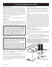
Connecting the Vent Pipe
Caution: Sharp edges. Always use gloves when installing.
Install the 3-inch flexible vent pipes down through the chimney.
Attach the pipe-to-cap adaptor to the termination cap and the
top of the flexible vent pipe, then install the cap to the top of the
chimney.
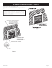
Remove the vent slide plate assembly from the top of the insert.
See Figure 7. Trim off excess venting then attach and secure
the bottom ends of the flex pipes to the starting collars with the
adjustable band clamps provided. Slide the gas insert into place,
and position any excess flex vent pipe back up into the chimney.
Begin installation of the insert into the fireplace opening. Align
the vent slide plate assembly with the guides located on top of
the insert. Work the insert inch by inch into the fireplace cavity
as you pull forward on the vent slide plate assembly. Do not use
excessive force on the vent slide plate. Once the vent slide plate
is close to seating, install the vent bolt through the center hole
of the insert top flange, and into the vent slide plate nut. Using
a wrench or socket, tighten the bolt until the vent slide plate is
seated forward completely.
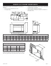
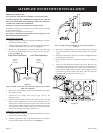
Positioning, Leveling, and Securing Insert
1. Place the insert into position.
Note: The front flanges of the insert (without surround panels)
should be set at approximately 1”(inch) in front of the face of the
fireplace.
2. Level the insert from side to side and front to back.
3. If necessary, use the leveling bolts included in the instruction
pack. Screw the legs into the nuts installed in the bottom of
the insert. Turn legs in until insert is level.
CAUTION: TO AVOID DOWNDRAFTS AND/OR COLD AIR
PROBLEMS, IT IS RECOMMENDED TO SEAL OFF THE
AREA BETWEEN THE TERMINATION CAP AND THE TOP
OF THE SOLID-FUEL CHIMNEY OPENING INTO WHICH
THE VENT CAP HAS BEEN INSTALLED.
Figure 7