


23552-4-0408 Page 25
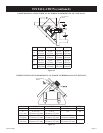
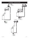
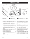
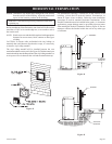
Figure 36
A = *Clearance above grade, veranda, porch, deck or balcony
[*12 inches (305 mm) minimum]
B = clearance to window or door that may be opened [*12 inches
(305 mm) minimum for appliances < 100,000 BTU/Hr
(30 kW)
C = clearance to permanently closed window [minimum
12 inches (305 mm) recommended to prevent condensation
on window]
D = vertical clearance to ventilated soffit located above the
terminal within a horizontal distance of 24 inches (610 mm)
from the center of the terminal [18 Inches (457 mm)
minimum
E = clearance to unventilated soffit [12 inches (305 mm)
minimum]
F = clearance to outside corner [See Page 24]
G = clearance to inside corner [See Page 24]
H = *not to be installed above a meter/regulator assembly within
3 feet (914 mm) horizontally from the center-line of the
regulator
I = clearance to service regulator vent outlet [*6 feet (1.89 m)
minimum]
J = clearance to non-mechanical air supply inlet to building or
the combustion air inlet to any other appliance [*12 inches
(305 mm) minimum for appliances ≤ 100,000 BTU/Hr (30
kW)
36 inches (914 mm) minimum for appliances > 100,000
BTU/Hr (30 kW)]
K = clearance to a mechanical air supply inlet [* 6 feet (1.89 m)
minimum]
L = †clearance above paved sidewalk or a paved driveway located
on public property [*7 feet (2.13 m) minimum]
M = clearance under veranda, porch, deck, or balcony [*12 inches
(305 mm) minimum ¥]
† a vent shall not terminate directly above a sidewalk or
paved driveway which is located between two single family
dwellings and serves both dwellings*
¥ only permitted if veranda, porch, deck, or balcony, is fully
open on a minimum of 2 sides beneath the floor*
* as specified in CGA B149 Installations Codes or ANSI
Z223.1. Note: Local Codes or Regulations may require
different clearances.
VENT CLEARANCES