Page 14 16009-1-0504
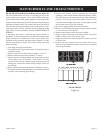
PILOT FLAME CHARACTERISTICS
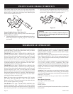
The correct flame will be blue and will extend beyond the
thermocouple. The flame will surround the thermocouple just
below the tip. A slight yellow flame may occur where the pilot
flame and main burner flame meet.
Figure 13
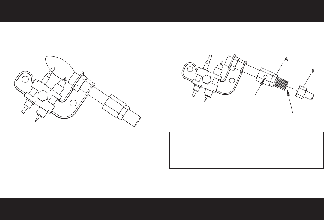
Oxygen Depletion Sensor Pilot (Figure 14)
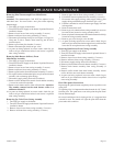
When the pilot has a large yellow tip flame, clean the Oxygen
Depletion Sensor as follows:
1. Clean the ODS pilot by loosening nut B from the pilot tubing.
When this procedure is required, grasp nut A with an open
end wrench.
2. Blow air pressure through the holes indicated by the arrows.
This will blow our foreign materials such as dust, lint and
spider webs. Tighten nut B also by grasping nut A.
Figure 14
Warning:
Never use needles, wires, or similar cylindrical objects to
clean the pilot to avoid damaging the calibrated ruby that
controls the gas flow.
THERMOSTAT OPERATION
To ignite main burner, turn gas control knob counterclockwise
toward HI setting. To shut down main burner, turn gas control
knob clockwise toward LO setting.
The SR-10T has an input of 10,000 BTUH (2.9KW/H). The
hydraulic thermostat bulb is located at the casing assembly
bottom. When the hydraulic thermostat bulb senses the need
for heat, the unit cycles “ON” at a full input rate of 10,000
BTUH (2.9KW/H). The unit remains at this full input rate until
the hydraulic thermostat bulb is “satisfied.” When the hydrau-
lic thermostat bulb is “satisfied” the burner will shut “OFF”
with the pilot flame remaining “ON.”
The SR-18T has an input of 18,000 BTUH (5.3KW/H). The
hydraulic thermostat bulb is located at the casing assembly
bottom. When the hydraulic thermostat bulb senses the need
for heat, the unit cycles “ON” at a full input rate of 18,000
BTUH (5.3KW/H). The unit remains at this full input rate until
the hydraulic thermostat bulb is “satisfied.” When the hydrau-
lic thermostat bulb is “satisfied” the burner will shut “OFF”
with the pilot flame remaining “ON.”
Note: The burner does not modulate between “ON” and the
pilot flame. When the SR-18T is “ON,” all three ceramic
plaques will “glow.” There will never be a time when only one
or two ceramic plaques are “glowing.”
The SR-30T has an input of 30,000 BTUH (8.8KW/H). The
hydraulic thermostat bulb is located at the casing assembly
bottom. When the hydraulic thermostat bulb senses the need for
heat, the unit cycles "ON" at a full input rate of 30,000 BTUH
(8.8KW/H). The unit remains at this full input rate until the
hydraulic thermostat bulb is "satisfied." When the hydraulic
thermostat bulb is "satisfied" the burner will shut "OFF" with the
pilot flame remaining "ON."
Note: The burner does not modulate between "ON" and the pilot
flame. When the SR-30T is "ON," all five ceramic plaques will
"glow." There will never be a time when only one or three ceramic
plaques are "glowing."
The LO and HI setting has temperature range of approximately
55°F (12.78°C) to 90°F (32.22°C), respectively. This is the
temperature at the hydraulic thermostat bulb not the room tem-
perature. The owner is advised to determine the particular heat
setting that is desired for comfort, as heating requirements are
different for every owner.
Attention: If the owner does not want the main burner to ignite
and turns the gas control knob to the LO setting, the main burner
will still ignite if the temperature at the hydraulic thermostat bulb
drops to 55°F (12.78°C).
If no heat is desired, turn the gas control knob to the PILOT
position.
Main Burner Operation
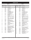
Description of Gas Control Knob:
OFF position.
PILOT position.
LO/HI will allow the hydraulic thermostat bulb to cycle the heater
ON and OFF.


