


Page 8 12425-7-0406
1. In selecting a location for installation, it is necessary to
provide adequate accessibility clearances for servicing and
proper installation.
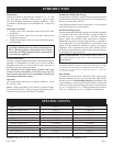
2. Clearances to combustible surfaces are 4" (102mm) from
sides, 12" (305mm) to top, 1 1/2" (38mm) from floor.
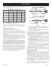
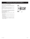
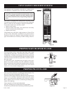
VENTILATION AND COMBUSTION AIR
Wall furnaces shall be installed in a location in which the facilities
for ventilation permit satisfactory combustion of gas and proper
venting under normal conditions. In buildings of conventional
frame, brick, or stone construction without tight storm windows
and doors, infiltration is normally adequate to provide air for
combustion and draft hood dilution.
Where appliances are installed in confined and unconfined spaces
within a building, the building being of unusually tight construction,
air for combustion and ventilation must be obtained directly from
outdoors or from such spaces that freely communicate with the
outdoors. Under these conditions, the confined and unconfined
spaces shall be provided with two permanent openings, one near
the top of the enclosure and one near the bottom; each opening
shall have a free area of not less than one square inch (6.45cm
2
)
per 2,000 BTU (.6KW/H) per hour of total input.
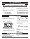
LOCATION - ALL MODELS
Select a location near the center of the space to be heated. Overflow
heat will circulate through doorways into adjacent rooms.
For large homes or spread-out floor plans, two or more furnaces are
recommended. Do not locate furnace where a door could swing
over the outer casing, or where circulation could be retarded by
furniture or cabinets.
Do not install in a closet, alcove or small hallway where the furnace
could be isolated by closing doors to the heated space.
When location is selected, check the walls, attic and roof to make
sure there are no obstructions such as pipes, electric wiring, etc.,
which would interfere with the installation of the furnace or vent
pipe.
NOTE: If Rear Register Kit is to be used, see Rear Register Kit
instructions for location of hole in rear wall. Register
outlet must be cut in wall before furnace is installed.
NOTE: If Optional Blower is to be used, hard wiring must be
completed for the optional blower prior to installation
of header plate.
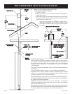
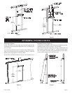
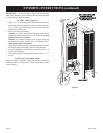
ROUGH-IN INSTRUCTIONS
Provide an opening in the wall 14 1/2" (368mm) wide and 66
1/8" (168cm) high measured from top of floor plate (See Figure
2 and Figure 3). Wall depth is to be 2" x 4" framing with 1/4"
(6.5mm) to 5/8" (16mm) sheeting. Attach baseplate (not supplied
with furnace) to header plate with sheet metal screws at each end.
Attach 4" (102mm) oval, double wall vent pipe to baseplate. Attach
enough vent pipe so that when installed in wall opening the vent
pipe will extend above the ceiling plate by at least 6" (152mm).
Install ceiling spacers according to manufacturer's instructions.
Insert header plate with attached 4" oval, double wall vent pipe
into wall opening. Position header plate at height shown in Figure
2. Locate rear edge of nailing flange at the back of the 2" x 4" stud
which will center the vent collar in the wall. Locate the angled
edge of header plate flush with the top of the wall opening. Nail
header plate to the wall studs.
NOTE: Minimum distance of 1 1/2" (38mm) must also be
maintained from top surface of carpeting, tile, etc.
CLEARANCES