Page 15R-2688
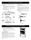
INSTALLING OPTIONAL BLOWER EEB-1. If heater is
installed on wall, in order to install optional blower, the
heater must be removed from wall.
1. Remove casing front assembly.
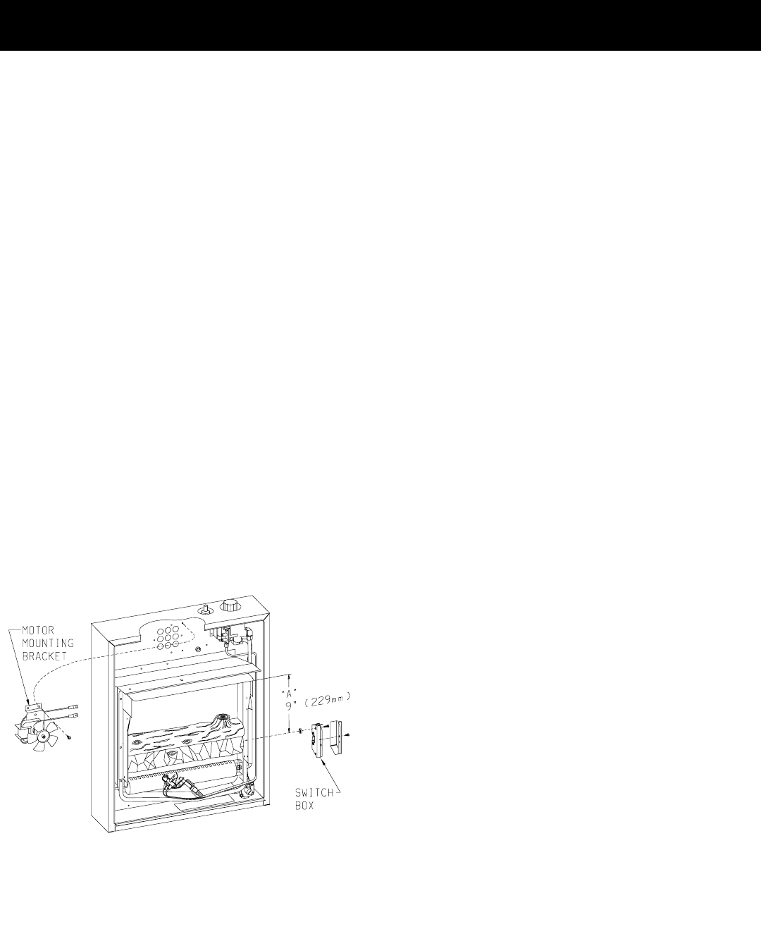
2. Align (2) clearance holes on motor mounting bracket with
(2) screw holes on casing assembly back and attach motor
mounting bracket with (2) #10 x 5/16" (8mm) screws
provided. The motor wires should be facing to the left and
then routed behind the motor mounting bracket and to the
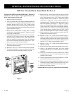
right as depicted in Figure 1.
3. Route cord set through 9/16" (14mm) hole on casing
assembly back. Insert approximately 3" (76mm) of cord set
into casing assembly back.
4. Attach the green ground wire from the cord set beneath one
of the #10 x 5/16" (8mm) screws on the motor mounting
bracket (see Step 2). Remove #10 x 5/16" (8mm) screw,
align ring terminal of green ground wire with clearance
hole on motor mounting bracket and replace #10 x 5/16"
(8mm) screw into motor mounting bracket.
5. Remove (2) #10 x 1/2" (13mm) screws from the right side
of the front shield assembly.
6. Remove (1) #10 x 1/2" (13mm) screw from the top shield.
7. Grasp front shield above screen assembly and pivot right
side of front shield forward approximately one inch.
Figure 1
8. Remove #8 x 3/8" (10mm) screw from switch box cover and
remove switch box cover from switch box. With fan control
wires facing upward, place 3/16" (5mm) spacer behind
oblong clearance hole on switch box. Locate 1/8" (3mm)
screw hole on right side of front shield assembly by
measuring down 9" (229mm) from the upper right corner of
the shield assembly (See Figure 1). Align 3/16" (5mm)
spacer and oblong clearance hole on switch box with 1/8"
(3mm) screw hole on right side of front shield assembly.
Attach (1) #10 x 1/2" (13mm) screw provided, by inserting
screw through oblong clearance hole and 3/16" (5mm)
spacer and into the right side of the front shield assembly.
9. Attach switch box cover to switch box with the #8 x 3/8"
(10mm) screw removed in Step 8.
10. Replace (1) #10 x 1/2" (13mm) screw removed in Step 5
into the top, right side of the front shield assembly. With the
installation of the switch box, the bottom, right side of the
front shield assembly does not require the replacement of
the #10 x 1/2" (13mm) screw removed in Step 5.
11. Replace (1) #10 x 1/2" (13mm) screw removed in Step 6
into the top shield.
12. Route fan control wires upward and beneath the gas valve.
13. Attach (1) pin terminal from black (hot) wire, smooth
insulation on cord set to (1) socket terminal on fan control
assembly.
14. Attach (1) pin terminal from black (neutral) wire, ribbed
insulation on cord set to (1) socket terminal from white
(neutral) wire on motor.
15. Attach (1) pin terminal on fan control assembly to (1) socket
terminal from black (hot) wire on motor.
16. Grasp cord set at casing assembly back and pull excess cord
set through casing assembly back and secure cord set in
casing assembly back with the strain relief provided.
17. Replace casing front assembly.
Attention: Be sure all wires are located away from fan blade.
EEB-1 for Unvented Room HeaterModel EE-25-(1, 2)
OPTIONAL BLOWER INSTALLATION INSTRUCTIONS


