


Web: http://www.enviromaster.comEnviromaster International LLC
3
WLC/WLH SPECIFICATIONS
NOTE: Due to ongoing development programs, design and specications may change without notice.
WLC/WLH SYSTEM OPTIONS
DISCHARGE AIR SPEED AND FLOW @ 230V
Model High CFM Low CFM Coil FPM Throw/Ft.
9/12 400 350 Dry 900 15
18/24 750 675 Dry 1,225 25
30/36 1,170 900 Dry 1,250 27
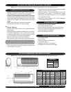
S1C/S1H
WLC/WLH
WLC/WLH
OBSERVED SOUND VALUES
(230V High Speed Fan)
Model dBA
09/12 45
18/24 56
30/36 60
WLC/WLH INTERCONNECTING-LINE SIZE
System Capacity
Btuh
Liquid
O.D.
Suction
O.D.
Condensate
I.D.
09 1/4” 1/2” 1/2”
12 1/4” 1/2” 1/2”
18 3/8” 5/8” * 1/2”
24 3/8” 3/4” 1/2”
30 3/8” 3/4” ** 1/2”
36 3/8” 3/4” ** 1/2”
*
WLC/WLH Suction Connection size is 3/4” O.D. and must bush down at the
WLC/WLH Unit.
** WLC/WLH Suction Connection size is 5/8” O.D. a factory supplied kit is provided
to transition to 3/4” O.D. interconnect.
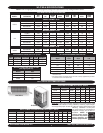
WLC/WLH ELECTRICAL SPECIFICATIONS
MODEL # VOLTS/HZ/PH
FAN
RLA
HP
HEATER
K.W.
AMPS
TOTAL
AMPS
MIN
VOLT
M.C.A.
HACR
BRKR
SMALL CABINET 09/12
09/12
115/60/1 0.64 0.02 – – 0.64 104 0.8 15
115/60/1 0.64 0.02 0.75 6.50 7.14 104 8.9 15
208/230/60/1 0.34 0.02 – – 0.34 197 0.4 15
208/230/60/1 0.34 0.02 3.00 13.04 13.38 197 16.7 20
MEDIUM CABINET 18/24
24
115/60/1 1.20 0.083 – – 1.20 104 1.5 15
115/60/1 1.20 0.083 0.75 6.52 7.72 104 9.7 15
115/60/1 1.20 0.083 1.25 10.90 12.10 104 15.1 20
208/230/60/1 0.56 0.070 – – 0.56 197 0.7 15
208/230/60/1 0.56 0.070 3.00 13.04 13.60 197 17.0 20
208/230/60/1 0.56 0.070 5.00 21.74 22.30 197 27.9 30
LARGE CABINET 30/36
30/36
208/230/60/1 0.80 1/10 – – 0.80 197 1.0 15
208/230/60/1 0.80 1/10 5.00 21.74 22.54 197 28.2 30
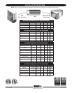
COOLING SYSTEMS WITH WALL UNITS
C o n d e n s e r Wall Unit Btuh SEER SHR EER
Ref.
S1C9 WLH09 9,000 13.0 .79 11.8
R22
S1C2 WLH12 12,000 13.0 .74 12 . 9
R22
S1C8 WLH24 18,000 14.0 .78 13.0
R22
S1C4 WLH24 24,000 13.0 .70 12.5
R22
S1C3 WLC36 30,000 13.0 .72 12.6
R22
S1C6 WLC36 33,600 13.0 .69 12 . 1
R22
* Important - This system has been designed and manufactured to meet
ENERGY STAR criteria for energy efciency. However, proper refriger-
ant charge and proper air ow are critical to achieve rated capacity and
efciency. Installation of this prod-
uct should follow the manufacturer’s
refrigerant charging and air ow in-
structions. Failure to
conrm proper charge
and airow may reduce
energy efciency and
shorten equipment life.
HEAT PUMPS SYSTEM OPTIONS WITH WALL UNITS
Condenser Wall Unit Cooling Btuh Heating Btuh SEER HSPF SHR EER COP
Ref.
S1H9 WLH09 9,000 8,600 13.0 8.0 .75 11.6 3.6
R22
S1H2 WLH12 11,400 10,600 13.0 8.0 .73 11.5 3.4
R22
S1H8 WLH24 18,000 16,400 13.0 7.7 .73 12.1 3.8
R22
S1H4 WLH24 23,000 20,600 13.0 8.3 .71 11.9 3.5
R22
*