


Made in Rome, New York, USAThe Ductless Split System of Choice
2
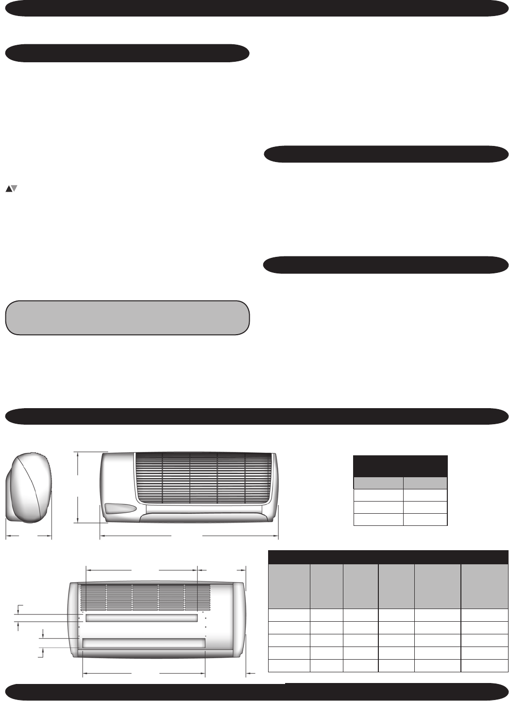
A
B
C
D
E
5 ¼”
1 ½”
2”
4 ⅜”
package. Deco panel, relay board, ribbon cables and
microprocessor all combined into one package.
• Integral condensate pump safety-switch connection
where-by the microprocessor monitors the condensate
pump safety switch and displays an error code when
a fault occurs. (Applys only with optional condensate
pump)
• CEC (California Energy Commission) compliant
• Condensate drain pan over ow protection
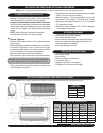
Cabinet Features:
• Durable ABS plastic cabinet with a galvanized steel
sub-chassis.
• Easily accessible, washable, reusable, nylon mesh lter.
• Horizontal discharge louver, constructed of high
temperature ABS plastic, that can be set to oscillate,
or can be parked in various pre-set positions.
• Manually adjustable vertical discharge ns.
• Easy access to pipe chase area from cabinet bottom.
Benet: Allows piping connections and condensate
pump installation with the unit mounted on the wall.
• Easily removable end-cap for access to control area
for installation and service.
• Condensate drain pan constructed of galvanized steel
(G90U), with anti-corrosion coating.
• Modular snap-in, 7-day programmable control with
large backlit LCD display, a “Change lter” display
feature and selectable Fahrenheit (Fº), or Centigrade
(Cº) temperature scale.
• Operational range between 55ºF to 90ºF, adjustable
in one-degree increments.
OPTIONAL EQUIPMENT
• Condensate pump (eld installed)
• 24V remote wall thermostat
• Electric heat with automatic reset high temperature
cutout and redundant high temperature fuse link
(when heat option is selected)
• Hand held infrared controller.
INSTALLER SUPPLIED ITEMS
• Low voltage wiring
• Power wiring
• Mounting screws and fasteners
• Condensate piping
• Refrigerant piping (if not supplied)
• Refrigerant (for interconnect charge)
STANDARD FEATURES Continued
WLC/WLH FEATURES AND OPTIONAL EQUIPMENT
NOTE: Due to ongoing development programs, design and specications may change without notice.
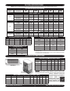
WLC/WLH DIMENSIONS AND SPECIFICATIONS
NOTE: Due to ongoing development programs, design and specications may change without notice.
WLC/WLH PHYSICAL DIMENSIONS
Model
“A”
Depth
“B”
Height
“C”
Length
“D”
Mounting
Bracket
Clearance
“E”
Tubing
Access
Clearance
WLH09 9 ⅞” 15 ¼” 38 ½” 24” 26 ½”
WLH12 9 ⅞” 15 ¼” 38 ½” 24” 26 ½”
WLH24 9 ⅞” 15 ¼” 48 ½” 34” 36 ½”
WLC30 9 ⅞” 15 ¼” 58 ½” 44” 46 ½”
WLC36 9 ⅞” 15 ¼” 58 ½” 44” 46 ½”
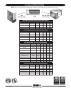
WLC/WLH
SHIPPING WEIGHT
Model Lbs.
WLH09/12
70
WLH18/24
108
WLC30/36
TBD