


4
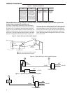
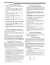
If you have a single stage compressor system see the dia-
gram below. A relay (customer provided) should be installed
as shown in Fig 7 to switch the fan speed to the next lower
speed on a call for dehumidification from the thermostat. The
reduction in air flow allows the coil to remove more humidity
from the air. The relay should be rated for blower motor load.
Since this configuration reduces the air flow in cooling, the
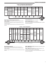
WIRING DIAGRAMS
anti-freeze-up control (White-Rodgers CAFC) or equivalent is
recommended. The CAFC prevents the air conditioning coil
from freezing due to low air flow, dirty filters, low refrigerant
pressure, etc. The CAFC snaps onto the suction line close to
the evaporator coil as possible and breaks the compressor
circuit when the suction line drops below 38 °F and re-make
the circuit at 46°F.
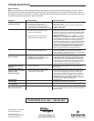
HOT
NEUTRAL
120 VAC
24 VAC
Relay
90-290Q
or equivalent
HOT
NEUTRAL
120 VAC
TRANSFORMER
R
HM
Humidifier
System
Figure 6 – Typical Wiring for 120V Humidifier System
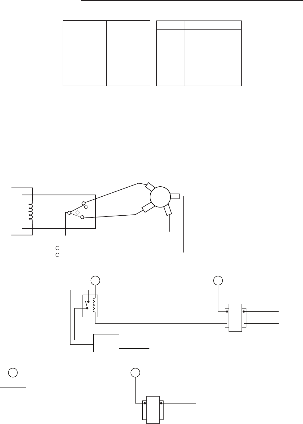
HOT
NEUTRAL
120 VAC
TRANSFORMER
HM
24 VAC
Humidifier
System
R
Figure 7 – Typical Wiring for 24V Humidifier System
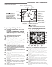
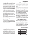
Dehumidification wiring without an electronically controlled variable speed blower system for
single stage compressor system only.
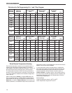
HM
DHM
Humidification Terminal,
Energizes on call for
heat if Humidity setpoint
is above room humidity.
Can also be used to
provide humidification
independent of a call for
heat and/or in cooling
mode if Automatic
Humidification is
selected in Configura-
tion Menu item #34
De-energizes on call for
Dehumidification to
lower the fan speed.
The DHM terminal is
only used on systems
with a compatible
dehumidification feature
that have the required
terminal connection on
the contol module or
have a relay installed to
lower the fan speed
+
S
-
Supply voltage
to remote
temperature
sensor
Remote
temperature
sensor signal
Supply voltage
to remote
temperature
sensor
Figure 4 – Humidity and Sensors
Relay
90-293Q
or equivalent
No
NC
“Heat Fan Output”
N
Dehum
Speed Fan
Med
DHM
N
Low
Normal High
“Cool Fan Output”
1
2
Normal Cool speed position (DHM energized)
Dehum speed mode (DHM de-energized)
1
2
Figure 5 – Typical Wiring for Dehumidifier System