


15
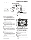
PROGRAMMING
TROUBLESHOOTING
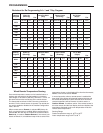
Averaging or Weighting Remote Sensors
The thermostat will weight or average the temperature of the
indoor remote sensor with the local sensor in the thermostat
for each program period. The averaging will be active only
when the local sensor and the indoor remote sensor are both
functional and enabled in the Installer/Configuration menu.
When the thermostat is in the Set Schedule mode, the weight
of the indoor sensor will be shown in the current temperature
digits of the display. The weight will show as A2 (average and
default), H4 (high) or L1 (low). Pressing the and keys at
the same time will change the weight for the program period.
The weight of the thermostat sensor is fixed.
In normal operation of the thermostat, the current tempera-
ture displayed will be the weighted average of the local
sensor and the remote sensor using the formula (local sensor
weight x local sensor temperature) + (remote sensor weight x
remote sensor temperature) / (local sensor weight + remote
sensor weight).
Example: Local sensor temperature is 80° and the remote
sensor is 70°.
If weight is selected H4, the averaged temperature of 72° will
be displayed.
(1 x 80) + (4 x 70) / 5 = 72°
If weight is selected A2, the average temperature of 73° will
be displayed.
(1 x 80) + (2 x 70) / 3 = 73.3°
If weight is selected L1, the average temperature of 75° will
be displayed.
(1 x 80) + (1 x 70) / 2 = 75°
The example shows that the weight selected would prioritize
the overall averaged temperature between the two sensors.
The high weight selection caused the remote sensor to have
a higher influence in the calculated temperature average than
the local sensor and the low weight selection caused the
remote sensor to have less influence.
Dual Fuel Temperature Setpoint
When the thermostat is configured for Heat Pump mode and
the Dual Fuel feature is selected on, the thermostat can moni-
tor the outside temperature using remote sensor F145-1378
or use software logic to determine when to switch to gas heat
and shut down the compressor. This eliminates the need for a
fossil fuel kit.
The user selectable temperature is called the dual fuel tem-
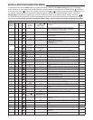
perature setpoint, dF and is set in the Installer/Configuration
menu, items 33 or 34. With outdoor remote sensor installed
and enabled, the dual fuel temperature setpoint (menu item
33) can be set to a temperature of -5° through 50°. When
outdoor remote sensor is not installed, a software logic
based dual fuel number (menu item 34) from 01 to 09 can be
selected. A higher temperature or dual fuel setting will provide
a smaller stage separation between the heat pump and Aux
to give more comfort. A lower temperature or number will
provide a larger stage separation for more economy.
After the dual fuel temperature setpoint is set and
is
pressed, a delay, Cd, can be set for compressor shutdown
after the auxiliary stage is energized. This delay can be set
from 0 seconds to 99 seconds to minimize the time that the
system may blow cooler air until the alternate source of heat
comes on. Default setting for delay is 60. When setting the
delay, if the or keys are held depressed, the setpoint
will increase or decrease at the rate of one degree every half
second for the first three seconds and double the speed after
three seconds.
Blower Balance Point for Heating
Requires DHM connection from thermostat to heat pump
system. Air to air heat pumps use a fast fan speed to circu-
late warm air for first stage heating. As outdoor temperatures
drop, the heat pump produces less heat and a high fan speed
makes the air from the ducts feel cooler. Blower Balance Point
allows you to select an outdoor temperature to slow the fan
speed so the air from the duct feels warmer. Select an out-
door temperature where the air from the ducts starts to feel
cool (Installer Configuration Menu item 37). When the outdoor
temperature drops to the selected temperature, the thermo-
stat will slow the fan speed so the outlet air feels warmer.
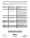
Comfort Alert Codes
The Comfort Alert diagnostics product monitors the air con-
ditioning outdoor systems with single phase Copeland Scroll
compressors. Abnormal system and electrical conditions are
indicated by flashing ALERT codes on the yellow LED on the
Comfort Alert module. The flash codes are transmitted to the
thermostat by the Comfort Alert Thermostat interface module.
The Comfort Alert compatible thermostat displays “Call For
Service” that flashes at the same rate as the yellow LED on
the Comfort Alert module.
Comfort Alert Codes
1 Flash Long run time
2 Flashs System pressure trip
3 Flashs Short cycling
4 Flashs Locked rotor
5 Flashs Open circuit
6 Flashs Open start circuit
7 Flashs Open run circuit
8 Flashs Welded Contactor
9 Flashs Low voltage