


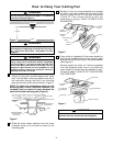
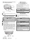
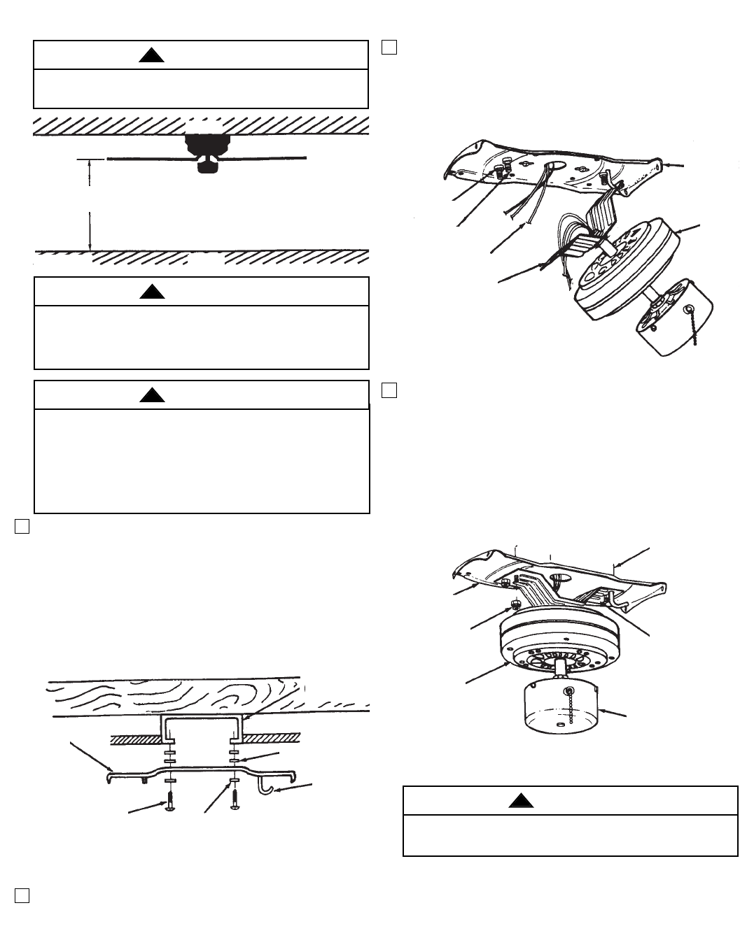
1. Securely attach the mounting plate to the outlet box
(Figure 2) using two screws (supplied with outlet
box). Pull the black, white and ground wires out of
the outlet box through the hole in the mounting
plate and lay them to the side as shown in Figure 3.
NOTE: For better fan performance make sure the
mounting plate is level. Additional washers (not
included) may be needed to insert between the
electrical box and mounting plate (Figure 2).
2. Slide the three rubber washers over the three
threaded studs on the bottom surface of the
mounting plate.
3. Carefully lift the fan motor assembly and engage
the slot in the motor bracket with the hook on the
mounting plate so that it is securely suspended
(Figure 3). Then connect wiring to your fan
according to section "HOW TO WIRE YOUR
CEILING FAN".
4. Once wiring is completed, lift the motor bracket so
that the four threaded studs on the mounting plate
protrude through the four slots in the motor bracket.
(See Figure 4.)
Securely tighten the three 1/4” locknuts (supplied)
onto the threaded studs, then try to shake the
motor bracket to ensure that the assembly is tight.
Proceed to section "HOW TO PUT YOUR CEILING
FAN TOGETHER".
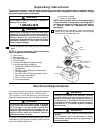
To reduce the risk of fire, electric shock, or personal
injury, mount fan to outlet box marked “Acceptable
for Fan Support”, and use screws supplied with
outlet box. Most outlet boxes commonly used for
support of light fixtures are not acceptable for fan
support and may need to be replaced. Consult a
qualified electrician if in doubt.
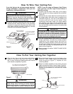
How to Hang Your Ceiling Fan
CEILING
FLOOR
AT LEAST
7'
Figure 1
4
OUTLET BOX
LEVELING WASHER
(IF REQUIRED)
HOOK
PLAIN WASHER
(SUPPLIED)
MOUNTING SCREWS
(SUPPLIED WITH
OUTLET BOX)
MOUNTING
PLATE
Figure 2
MOTOR
MOUNTING
PLATE
MOTOR
BRACKET
SUPPLY WIRE
LEADS
THREADED
STUDS
RUBBER
WASHER
Figure 3
The fan must be hung with at least 7' of clearance
from floor to blades (Figure 1).
WARNING
!
The outlet box and joist must be securely anchored
and capable of supporting at least 50 lbs. Use only a
U.L. outlet box marked as “Acceptable for Fan
Support”.
WARNING
!
MOUNTING
PLATE
1/4" LOCKNUTS
(3) (SUPPLIED)
FAN MOTOR
SWITCH HOUSING
MOTOR BRACKET
OUTLET BOX
Figure 4
WARNING
!
To avoid possible fire or shock, do not pinch wires
between the motor bracket and mounting plate.
WARNING
!