


4
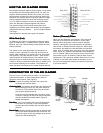
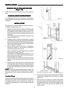
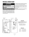
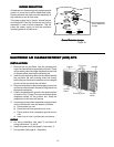
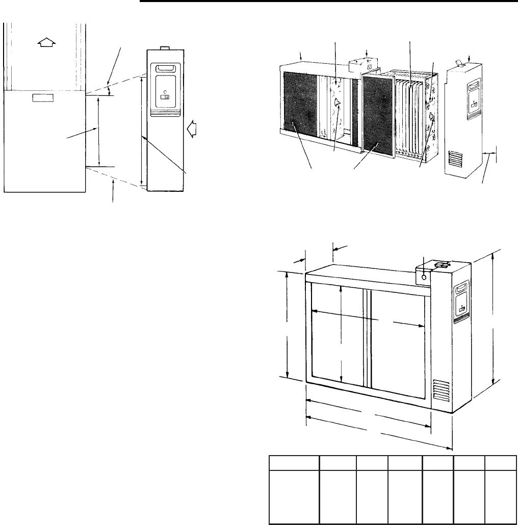
Air Flow
Furnace
Opening
Not to Exceed 20
Air Flow
Electronic
Air Cleaner
Opening
Electronic
Air Cleaner
Furnace
Transition Section
(if Needed)
Figure 3
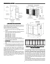
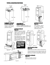
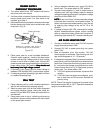
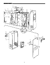
Cabinet
(Interchangeable)
Collecting Cell
(Interchangeable)
Collecting Cell
Outlet Box
Power Pack
Handle
Contact
Button
Contact
Button
Pre-Filters
(Interchangeable)
See text for Cell
Removal Clearance
Figure 4
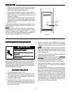
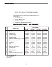
SST1000 24 3/4 21 5/16 18 5/8 13 9/16 16 7/16 19 1/16
SST1400 29 11/16 26 1/4 23 5/8 13 9/16 16 7/16 19 1/16
SST1600 25 1/2 21 5/16 18 5/8 17 3/4 20 5/8 23 3/8
SST2000 29 11/16 26 1/4 23 5/8 17 3/4 20 5/8 23 3/8
MODEL NO. A B C D E F
Figure 5
LOCATING THE AIR FILTERLOCATING THE AIR FILTER
LOCATING THE AIR FILTERLOCATING THE AIR FILTER
LOCATING THE AIR FILTER
Your air filter must be mounted in the return air duct of a
central forced-air system, on the air entering side of your
furnace. (See Figure 3 for example.)
Select a location that meets the following:
1. The face of the cell will be at a right angle to the air
stream.
2. Allow the following clearances to permit removal of
cells and pre-filters: (See Figures 4 and 5)
Model SST1000 - 14 inches
Model SST1400 - 15 inches
Model SST1600 - 14 inches
Model SST2000 - 15 inches
For complete dimension data refer to Figure 5.
3. The air filter is not to be placed in the discharge of
either the heating or cooling unit.
4.
IMPORTANT: IMPORTANT:
IMPORTANT: IMPORTANT:
IMPORTANT: If atomizing spray type humidifier is
used, it must be installed downstream from the air
filter.
5. If the air cleaner has a power cord installed, unit must
be located close enought to the outlet so connection
can be made without the use of an extension cord.
If your furnace duct system has a pre-installed boot,
discard front cover of boot and slide the air cleaner
component inside the boot. For installation of Air Cleaner
Retrofit (ACR) kits, see page 13.
If furnace opening cannot be enlarged to required size, a
transition sheet metal section must be used. Transition
must be planned for each job. Reduction should not be
more than 4 inches per linear foot, approximately 20
angular degrees (Figure 3).
PREINSTPREINST
PREINSTPREINST
PREINST
ALLAALLA
ALLAALLA
ALLA
TIONTION
TIONTION
TION
6 7/8"
A
B
E
D
F
C
Knockouts for
3/4" Conduit
(three sides)
DIRECTION OF AIR FLOW THROUGHDIRECTION OF AIR FLOW THROUGH
DIRECTION OF AIR FLOW THROUGHDIRECTION OF AIR FLOW THROUGH
DIRECTION OF AIR FLOW THROUGH
THE AIR CLEANERTHE AIR CLEANER
THE AIR CLEANERTHE AIR CLEANER
THE AIR CLEANER
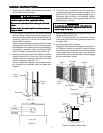
Your air cleaner is shipped from the factory with air flow
from left-to-right. If this air flow is suitable for the
installation, no further changes need to be made (Fig-
ure 4). For right-to-left air flow, remove both pre-filter
and cell sections. Turn cells upside down (with the
same end facing the cabinet opening). This will locate
the ionizing wires at the right, and both contact buttons
and cell handles will be facing the power door. Air flow
direction must agree with arrow embossed on end of
collecting cells.
After installing the cell sections, install pre-filters in cabinet
tracks on the right. This will again place the pre-filters on
the air entering side (on the same side as ionizing wires).