


2. Slide the four switch levers on the code
switch to your choice of ON (up) or
down positions. Use a ball-point pen or
small screwdriver and slide the levers
firmly up or down.
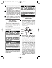
3. In the receiver (Figure 1), slide the four
switch levers to the same positions as
set in the transmitter. Make sure the
levers on both switches are in the same
positions, otherwise the fan will not
operate.
4. Position the battery in the transmitter
battery compartment and replace the
battery cover.
CEILING FAN
PROCEDURES
Electrical Requirements
Your new ceiling fan will require a ground-
ed electrical supply line of 120 volts AC,
60 Hz, 15 amp circuit.
The outlet box must be securely anchored
and capable of withstanding a load of at
least 50 pounds.
5
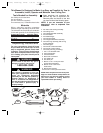
To reduce the risk of fire, electric
shock, or personal injury, mount fan
to outlet box marked “Acceptable for
Fan Support”, and use screws sup-
plied with outlet box. Most outlet
boxes commonly used for support of
light fixtures are not acceptable for
fan support and may need to be
replaced. Consult a qualified electri-
cian if in doubt.
!
WARNING
Turning off wall switch is not suffi-
cient. To avoid possible electrical
shock, be sure electricity is turned off
at the main fuse box before wiring. All
wiring must be in accordance with
National and Local codes and the ceil-
ing fan must be properly grounded as
a precaution against possible electri-
cal shock.
!
WARNING
How to Assemble Your
Ceiling Fan
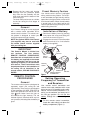
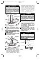
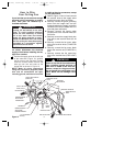
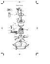
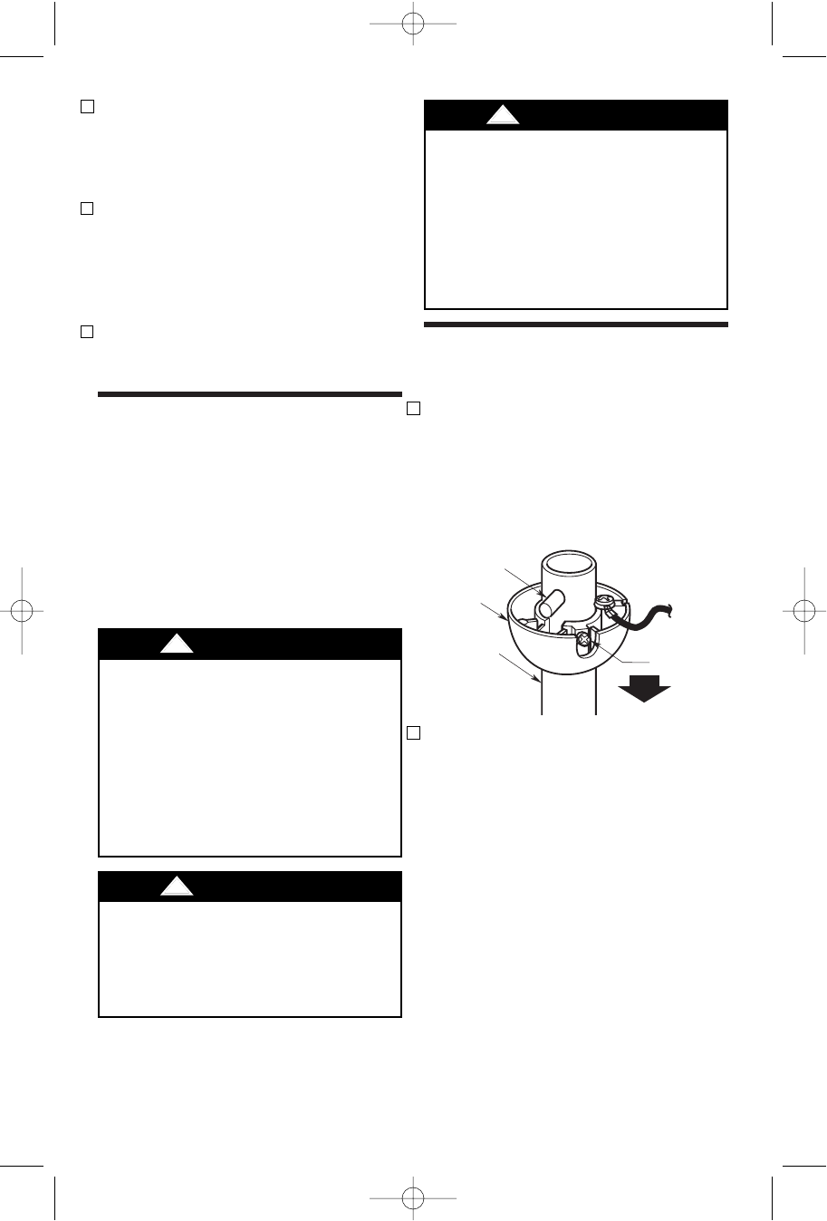
1. Remove the hanger ball by loosening
the setscrew in the hanger ball until the
ball falls freely down the downrod
(Figure 2). Remove the pin from the
downrod, then remove the hanger ball.
Retain the pin and hanger ball for rein-
stallation in step 5.
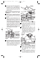
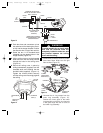
2. Unscrew the two upper setscrews
(Figure 3) until they clear the inside of
the motor coupling. Then separate,
untwist and unkink the three 80” motor
leads. Route the motor lead wires
through the downrod. Align the clevis
pin holes in the downrod with the holes
in the motor coupling. Install the clevis
pin and secure with the hairpin clip
(Figure 3). The clevis pin must go
through the holes in the motor coupling
and the holes in the downrod. Be sure
to push the straight leg of the hairpin
clip through the hole near the end of
the clevis pin until the curved portion of
the hairpin clip snaps around the clevis
pin. The hairpin clip must be properly
installed to prevent the clevis pin from
working loose. Pull up on the downrod
to make sure the clevis pin is properly
installed.
To avoid possible fire or shock, fol-
low all wiring instructions carefully.
Any electrical work not described in
these instructions should be done or
approved by a licensed electrician.
!
WARNING
If your fan is to replace an existing ceiling
light fixture, turn electricity off at the main
fuse box at this time and remove the exist-
ing light fixture.
PIN
HANGER
BALL
SETSCREW
DOWNROD
Figure 2
BP7284, Sturbrige, KF180 7/31/06 10:52 AM Page 5