


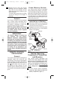
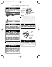
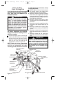
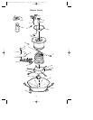
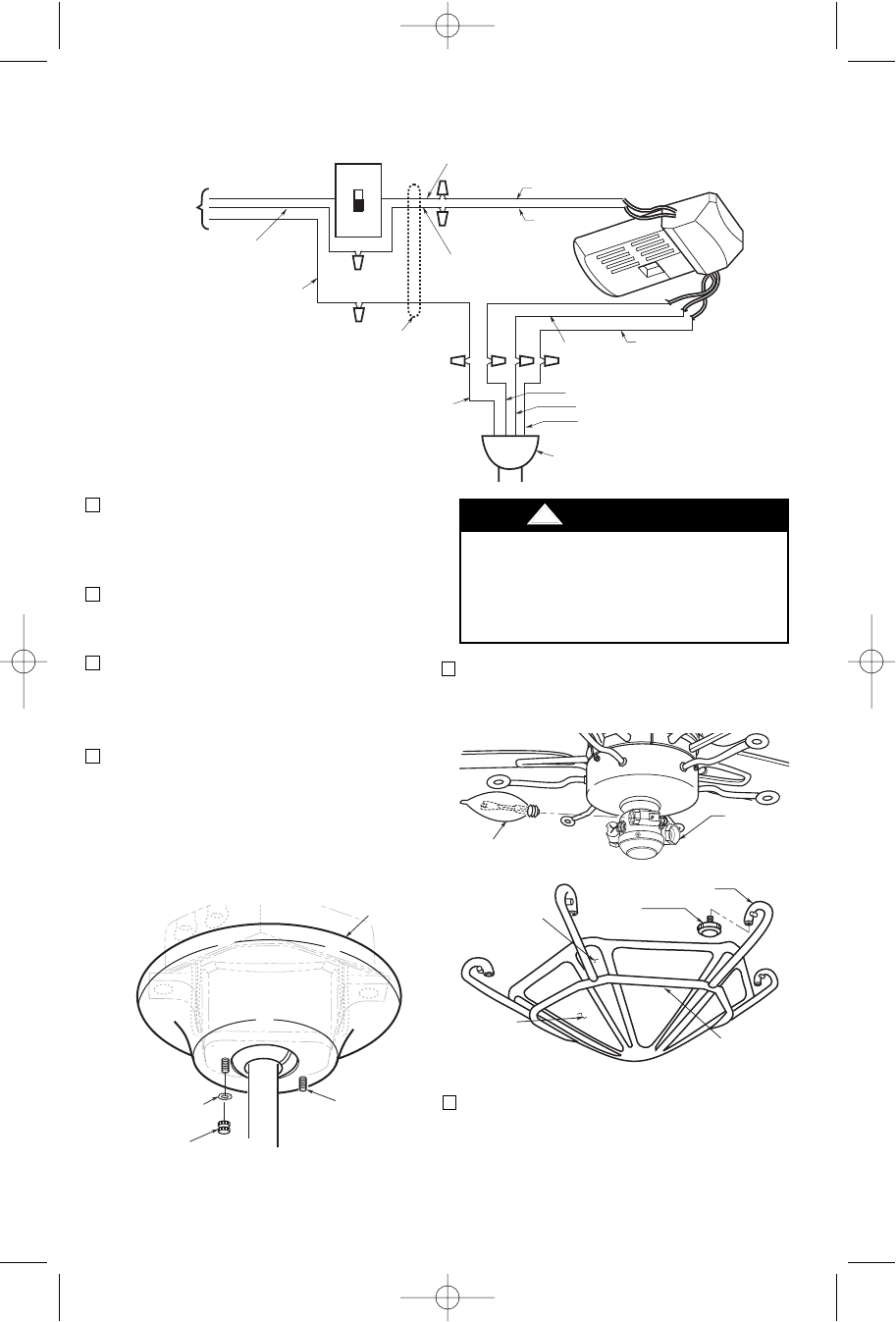
7. Screw three 60-watt (maximum) cande-
labra base flame bulbs into the light
fitter sockets (Figure 15).
8. Unscrew the six ring screws from the
lower ring assembly (Figure 15).
Position the lower glass in the lower
ring assembly so that the six channels
in the glass align with the six arms of
the lower ring assembly.
ARM
LIGHT
FITTER
RING
SCREWS (6)
CHANNEL
LOWER
GLASS
LOWER RING
ASSEMBLY
60-WATT
CANDELABRA
BASE BULB (3)
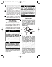
To avoid possible fire or shock, make
sure that the electrical wires are
completely inside the outlet box and
not pinched between the ceiling
cover and the ceiling.
!
WARNING
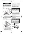
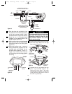
STANDARD ON-OFF WALL
SWITCH OR OPTIONAL SW101
WALL CONTROL
BLACK
BLACK
WHITE
RED
BLACK
WHITE
HANGER BALL
GREEN WIRE (GROUND)
FROM HANGER BALL AND
HANGER BRACKET
TWO-CONDUCTOR
CABLE (WITH
GROUND)
BLACK
(HOT)
WHITE
GROUND
TO
120-
VOLT
SUPPLY
WHITE
BLUE
WHITE
BLUE
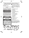
Figure 13
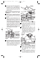
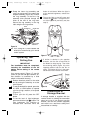
3. Push the wires and connectors up into
the outlet box while inserting the receiv-
er fully into the hanger bracket. Position
the antenna wire on top of the receiver.
4. Screw the two 1-1/4” threaded studs
(supplied) into the tapped holes in the
hanger bracket (Figure 12).
5. Lift the ceiling cover up to the threaded
studs and turn until the studs protrude
through the holes in the ceiling cover
(Figure 14).
6. Secure the ceiling cover in place by
sliding lockwashers (supplied) over the
threaded studs and installing the two
knurled knobs (supplied). (Figure 14).
Tighten the knurled knobs securely
until the ceiling cover fits snugly against
the ceiling.
THREADED
STUD (2)
CEILING
COVER
KNURLED
KNOB (2)
LOCKWASHER
(2)
Figure 14
Figure 15
10
BP7284, Sturbrige, KF180 7/31/06 10:52 AM Page 10