


EC2-391_65136_EN_R01.doc Replacement for 00 3 / 4 PCN: 865 022 21.09.2007
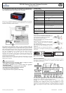
EC2-391 Display Case and Coldroom Controller
Operating Instructions
GB
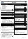
List of Parameters
/ DISPLAY PARAMETERS
Min Max Unit Def.
Custom
/1 Value to show 0 9 - 0
0 = Thermostat control temperature with Temp. alignment °C
1 = Air-in temperature °C
2 = Air-out temperature °C
3 = Alarm temperature °C
4 = Defrost termination temperature °C
5 = Coil-in temperature °C
6 = Coil-out temperature °C
7 = Calculated superheat °K
8 = Valve opening in %
9 = Displays defrost status
/2 Alarm suppression 0 = off, 1 = on 0 1 - 0
/5 Temperature Unit 0 = °C, 1 = °F 0 1 - 0
/6 Decimal point 0 = yes, 1 = no 0 1 - 0
/7 Display during defrost 0 2 - 0
0 = dF (= defrost mode); 1 = dF + defrost termination temp.
2 = dF + control temperature
/C Temperature alignment for /1=0 -20 20 K / °F 0.0
A ALARM-PARAMETERS
A0 Mean factor alarm temperature 0 100 % 100
A1 Low temp alarm delay 0 180 min 5
A2 High temp alarm delay 0 180 min 5
A3 Alarm delay after defrost 0 180 min 10
AH
High temp alarm limit AL 70 °C / K 40
AL Low temp alarm limit -55 AH °C / K -50
At Alarm limit type 0 1 - 0
0=absolute temperatures °C; 1= relative temperatures K to setpoint
r THERMOSTAT-PARAMETERS
r1 Min setpoint -50 r2 °C -50
r2 Setpoint max r1 60 °C 40
r3 Day/night control 0 = off, 1 = on 0 1 - 1
r4 Thermostat mode 0 4 - 1
0 = off, no thermostat function, continues cooling air in sensor monitoring
off, no temp. alarms generated
1 = cooling, deadband control: cut in = set-point + difference
cut out = set-point
2 = cooling, modulating thermostat: cut in = set-point
cut out = set-point – difference /2
3 = heating, deadband control: cut in = set-point – difference
cut out = set-point
4 = on, external control using nvi Valve via SNMP. Air in and air out sensor
monitoring off. Temp. alarms will be generated
r6 Setpoint night r1 r2 °C 4.0
r7 Differential night 0.1 20.0 K 2.0
r8 Mean factor, day operation 0 100 % 100
r9 Mean factor, night operation 0 100 % 50
rd Differential day 0.1 20.0 K 2.0
St Setpoint day r1 r2 °C 2.0
d DEFROST PARAMETERS
d0 Defrost mode 0 2 - 1
0 = natural defrost, defrost heater not activated
pulsed defrost not possible
1 = forced defrost, defrost heater activated, pulsed
defrost possible
2 = forced defrost, defrost heater activated, pulsed defrost possible,
defrost termination using nviStartUp via SNMP
d1 Termination by: 0 3 - 0
0 = termination by temperature,
termination by time will generate an alarm
1 = termination by time,
termination by temperature will generate an alarm
2 = first, what ever comes first time or temperature, no alarm
3 = last, by time and temperature, no alarm
d2 Defrost termination sensor 0 1 - 1
0 = Dedicated defrost sensor must be installed
1 = Air-out sensor used for defrost termination
d3 Pulsed defrost 0 1 - 0
0 = off, no pulsed defrost, heaters switched off at defrost termination
temperature dt or max. time dP whatever is selected
1 = on, pulsed defrost, dd and dH in use, heaters are switched off at
dH and switched on again at dH – dd
d4 Defrost at startup 0 = no, 1 = yes 0 1 - 0
d5 Delay power up defrost 0 180 min 0
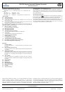
Min Max Unit Def.
Custom
d6 Pump down delay 0 180 sec 0
Compressor will run during pump down delay while valve is closed
d7 Drain delay 0 15 min 2
d8 Injection delay 0 180 sec 0
Valve is open during injection delay while compressor is not running
d9 Demand defrost mode
0 = off, 1 = on, 2 = on together with
timed defrost
0 2 - 0
dd Pulsed defrost differential 1 20 K 2
dH Pulsed defrost setpoint -40 dt °C 5
dt Defrost termination temperature -40 90 °C 8
dP Max defrost duration 0 180 min 30
dI Defrost interval 0 192 h 8
du Start up delay after synch 0 180 min 30
F FAN-PARAMETERS
F1 Fan startup by: 0 = on 0 4 - 0
1 = delayed by time Fd, error on temperature
2 = by temperature Ft, error on time
3 = first, whatever comes first time or temperature, no alarm
4 = last, time and temperature must come, no alarm
F2 During no cooling 0 3 - 0
0 = on; 1 = off; 2 = delayed by F4; 3 = off, when door open
F3 During defrost 0 = on, 1 = off 0 1 - 0
F4 Stop delay time 0 30 min 0
F5 During cleaning 0 = off, 1 = on 0 1 - 0
Fd Fan delay after defrost 0 30 min 0
Ft On temp after defrost -40 40 °C 0
u SUPERHEAT PARAMETERS
u0 Refrigerant 0 = R22 1 = R134a
2 = R507 3 = R404A 4 = R407C
5 = R410A 6 = R124 7 = R744A
0 7 - 3
u1 Correction glide / dp
Glide = positive values
Pressure drop = negative values
-20.0 20.0 K 0.0
u2 MOP control
0 = MOP off, 1 = MOP on
0 1 - 0
u3 MOP temperature -40 40 °C 0
u4 Superheat mode 0 = off
1 = fixed superheat
2 = adaptive superheat
0 2 - 1
u5 Superheat init setpoint u6 u7 K 6
u6 Superheat setpoint min. 3 u7 K 3
u7 Superheat setpoint max. u6 20 K 15
uu Start opening 25 75 % 30
DIGITAL INPUT PARAMETERS
i0 S5 input 1 = inverse function 0 1 - 0
∩0 Functions for S5 0 = normal input 0 8 - 0
1 = cleaning
2 = only fan
3 = door contact
4 = permanent cooling
5 = day / night switch
6 = compressor safety chain
7 = defrost request
8 = defrost inhibited
DIGITAL OUTPUT PARAMETERS
o0 Output 1 = inverse function 0 1 - 0
n0 Functions for output 1 = alarm 0 1 - 0
H OTHER PARAMETERS
H2 Display access 0 4 - 3
0 = all disabled (Caution: access to controller only via LON
network possible)
1 = Keyboard enabled
2 = IR remote control enabled
3 = Keyboard and IR remote control; Temporary data display and
manual defrost enabled.
4 = Keyboard and IR remote control; Temporary data display
disabled. Control setpoint with SEL key and manual defrost
enabled.
H3 IR access code 0 199 - 0
H5 Password 0 199 - 12