


EC2-391_65136_EN_R01.doc Replacement for 00 2 / 4 PCN: 865 022 21.09.2007
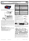
EC2-391 Display Case and Coldroom Controller
Operating Instructions
GB
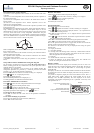
Recommended Sensor Positions in Detail:
(1) ECN-Pxx coil-in temperature sensor: Position on the first return bend of the
evaporator.
(2) ECN-Pxx coil-out temperature sensor: Position directly after the evaporator on
the common suction line.
(3) ECN-Pxx air-in temperature sensor: Position in the middle of the cabinet as
high as possible.
(4) ECN-Pxx air-out temperature sensor: Position asymmetric closer to the
expansion valve as high as possible.
(5) ECN-Fxx fin temperature sensor: Position on the evaporator, asymmetric closer
to the expansion valve.
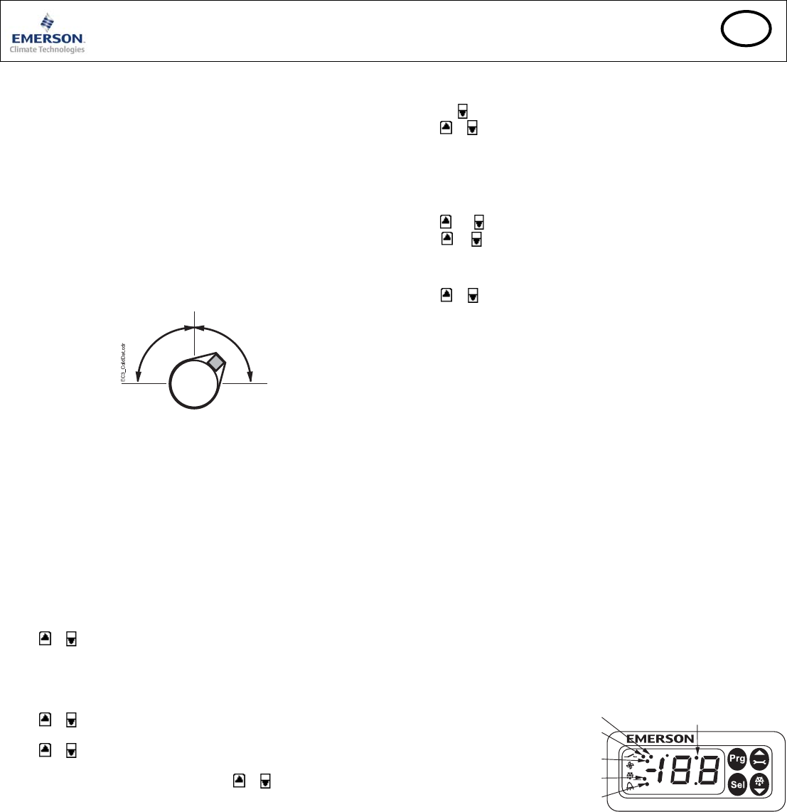
Recommendations for mounting the pipe sensor: Insure proper thermal contact by
using a metallic pipe clamp or temperature resistant plastic straps. Do not use
standard plastic tie wraps (as used for electrical wiring) as they may become loose
over time, which could result in faulty temperature measurements and poor
superheat control performance. It is recommended to insulate the pipe temperature
sensor with ARMAFLEX™ or equivalent. The recommended position of the pipe
sensors is between 9 and 3 o’clock as shown in the picture.
Both air temperature sensors should be mounted on spacers in the air duct so that
there is airflow around.
Caution: The sensor cables can be extended if necessary. The connection must be
protected against water and dust.
The evaporator outlet temperature sensor should be mounted on the common
suction header of the evaporator.
A calibration correction can be made using the parameter u1 (see procedure
below).
Setup and Parameter Modification Using the Keypad
For convenience, an infrared receiver for the optional IR remote control unit is
build-in, enabling quick and easy modification of the system parameters when a
computer interface is not available.
Alternatively, the parameters can be accessed via the 4-button keypad. The
configuration parameters are protected by a numerical password. The default
password is “12”. To select the parameter configuration:
• Press the PRG button for more than 5 seconds, a flashing “0” is displayed
• Press
or until “12” is displayed (password)
• Press SEL to confirm password
The first modifiable parameter code is displayed (/1).
To modify parameters see Parameters modification below.
Parameter Modification: Procedure
• Press or to show the code of the parameter that has to be changed;
• Press SEL to display the selected parameter value;
• Press
or to increase or decrease the value;
• Press SEL to temporarily confirm the new value and display its code;
• Repeat the procedure from the beginning "press
or to show..."
To exit and save the new settings:
• Press PRG to confirm the new values and exit the parameters modification
procedure.
To exit without modifying any parameter:
• Do not press any button for at least 60 seconds (TIME OUT).
• Press “ESC” on IR remote control.
Defrost Activation:
A defrost cycle can be activated locally from the keypad:
• Press the
button for more than 5 seconds, a flashing “0” is displayed
• Press
or until “12” is displayed (password)
• Press SEL to confirm password
The defrost cycle is activated.
Special Functions:
The Special Functions can be activated by:
• Press
and together for more than 5 seconds, a flashing “0” is displayed.
• Press
or until the password is displayed (default = 12). If password was
changed, select the new password.
• Press SEL to confirm password, a “0” is displayed and the Special Function
mode is activated.
• Press or to select the function. The number of special functions is dynamic
and controller dependent. See list below.
• Press SEL to activate the function without leaving the special function mode.
• Press PRG to activate the function and leave the special function mode.
Most of the Special Functions work in a toggle mode, the first call activates the
function, and the second call deactivates the function.
The indication of the function can only be displayed after exiting the special
function mode.
• 0: Display test function
• 1: Clear alarm messages
• 2: Cleaning mode. The cleaning mode is effectively a manual defrost with the
option of the fans on/off. The cleaning mode should not be used in order to
isolate the application for maintenance purposes.
• 3: Fans only
• 4: Set the electronic control valve to 100% open
• 5: Resets all parameters to the factory default setting. The controller will
indicate “oF” during the reset and the valve will close.
Display of Data:
The data to be shown on the display can be selected by the user. In case of an
alarm, the alarm code is displayed alternately with the selected data. The user can
inhibit the alarm code. Press the SEL button to scroll through all possible
displayable data.
The display will show for one second the numerical identifier of the data and then
the selected data. After two minutes the display will return to the by parameter /1
selected data.
It is possible to temporarily display the values of the different sensors. This is a
useful feature when initially setting-up the system without the aid of the
WebPages. Press the SEL sequentially. The value displayed on the screen
corresponds to the number corresponding to the /1 parameter. Action only valid
when parameter H2 = 3.
Logical status of lighting relay
LON service LED
Logical status of fan relay
Logical status of defrost heater relay
Alarm condition
IR LED