


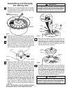
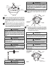
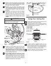
3. Screw the two threaded studs (supplied) into the
tapped holes in the hanger bracket (Figure 9).
4. Lift the ceiling cover up to the threaded studs and
turn until studs protrude through the holes in the
ceiling cover (Figure 10).
5. Secure the ceiling cover in place by sliding #8
lockwashers over the threaded studs and installing the
two knurled knobs (supplied). (Figure 10). Tighten the
knurled knobs securely until the ceiling cover fits
snugly against the ceiling and the hole in the ceiling
cover is clear of the downrod.
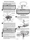
If you feel that you do not have enough electrical
wiring knowledge or experience, have your fan
installed by a licensed electrician.
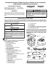
1. Connect the green grounding lead from the hanger
ball and the green grounding lead from the hanger
bracket to the grounding conductor of supply (this
may be a bare wire or wire with green colored
insulation) (Figure 9). Securely connect the wires
using wire connector supplied.
2. Securely connect the fan motor white wire to the
supply white (neutral) wire using wire connector
supplied (Figure 9). Securely connect the fan motor
black wire and blue wire to the supply black (hot)
wire using wire connector supplied (Figure 9). After
connections have been made, turn leads upward
and carefully push leads into the outlet box, with
the white and green leads on one side of the outlet
box and the black and blue leads on the other side
of the outlet box.
6
Wiring Your Ceiling Fan
To avoid possible electrical shock, be sure electricity
is turned off at the main fuse box before wiring.
NOTE: If you are not sure if the outlet box is ground-
ed, contact a licensed electrician for advice, as it
must be grounded for safe operation.
NOTE: CEILING COVER
OMITTED FOR CLARITY.
GROUND
WIRE
LISTED
WIRE
CONNECTOR (3)
GREEN WIRE
(GROUND) FROM
HANGER BRACKET
GREEN WIRE
(GROUND) FROM
HANGER BALL
WHITE SUPPLY
(NEUTRAL)
WHITE FAN
WIRE
BLACK SUPPLY
(HOT)
BLACK AND BLUE
FAN WIRES
THREADED
STUD (2)
Check to see that all connections are tight, including
ground, and that no bare wire is visible at the wire
connectors, except for the ground wire.
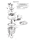
CEILING COVER
#8 LOCKWASHER
KNURLED KNOB
THREADED STUD
To avoid possible fire or shock, make sure that the
electrical wires are completely inside the outlet box
and not pinched between the ceiling cover and the
ceiling.
Final Assembly of the
Ceiling Fan
Figure 9
Figure 10
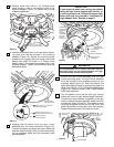
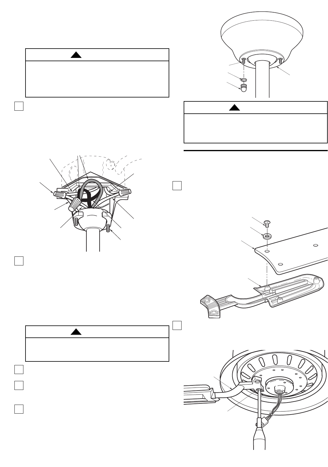
1. Mount the blade flange to the blade using three
3/16-24 x 5/16” slotted Phillips head screws and
three M5 flat washers (supplied) (Figure 11).
Repeat this procedure for the remaining five blades.
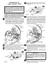
2. Install one blade assembly to the motor hub using
two 1/4-20 x 1/2” Phillips oval head screws
(Figure 12). Repeat this procedure for the
remaining five blade assemblies.
WARNING
!
WARNING
!
WARNING
!
M5 FLAT WASHER (3)
3/16-24 x 5/16" SLOTTED
PHILLIPS HEAD SCREW (3)
BLADE
BLADE FLANGE
Figure 11
1/4-20 x 1/2" PHILLIPS
OVAL HEAD SCREW
(2 PER BLADE FLANGE)
BLADE
ASSEMBLY
Figure 12