


8
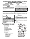
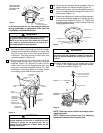
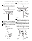
17. The blade flanges have an interlocking feature
that must be fully engaged before tightening the
screws. Make sure all the flanges are properly
engaged and then tighten the flange screws.
If one of the flanges does not seat properly on
the motor hub, loosen the adjacent flange
screws, re-engage and reseat the flanges, then
tighten the screws again.
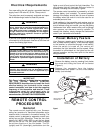
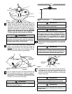
18. Engage the motor connector with the connector
in the remote control receiver (Figure 14). The
two connectors are keyed and must be mated
correctly before they can be engaged.
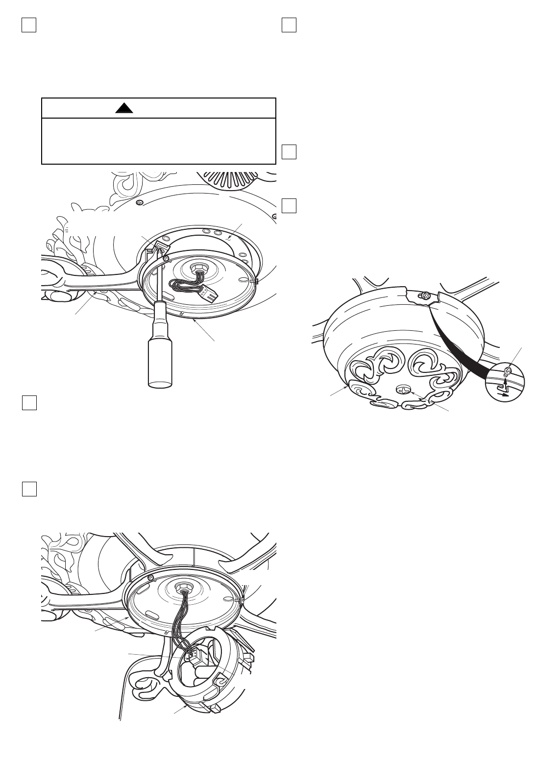
MOTOR
HUB
1/4-20 x 1/2" FLANGE SCREWS
(INSTALL THROUGH SLOTS
IN SWITCH HOUSING PLATE)
BLADE
FLANGE
SWITCH HOUSING
PLATE
Figure 13
REMOTE CONTROL
RECEIVER
MOTOR CONNECTOR
SWITCH HOUSING
PLATE
MOUNTING
SCREW (3)
RECEIVER
CONNECTOR
Figure 14
16. Rotate the motor hub until the flange screw holes
are visible through the slots in the switch housing
plate. Loosely attach one blade assembly to the
motor hub using two 1/4-20 x 1/2” flange screws
(Figure 13). Make sure the screws are NOT
tightened. Repeat this procedure for the other
four blade assemblies.
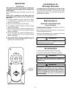
19. Remove one of the mounting screws from the
switch housing plate (Figure 14) and loosen the
other two screws several turns.
NOTE: If you are installing an Emerson Light
Fixture with your fan, refer to the Light Fixture
Owner’s Manual and proceed as follows. Remove
the center screw from the switch housing and
install the light fitter in the threaded hole.
Connect the blue wire from the light fitter to the
receiver blue wire, and the white wire from the
light fitter to the receiver white wire.
20. Remove the protective paper from the three
adhesive blocks in the switch housing.Then posi-
tion the remote control receiver securely onto the
three adhesive blocks, making sure the antenna
wire is uncoiled in the switch housing.
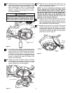
21. Engage the two slots in the switch housing with
the two loosened mounting screws in the switch
housing plate (Figure 15). Rotate the switch
housing to the right, then tighten the two mount-
ing screws and install the other mounting screw
previously removed in Step 19.
CENTER
SCREW
MOUNTING
SCREW (3)
SWITCH
HOUSING
Figure 15
To reduce the risk of personal injury, do not bend the
blade flange when installing the blade flanges,
balancing the blades or cleaning the fan. Do not
insert foreign objects in between rotating fan blades.
WARNING
!