


7
The outlet box and joist must be securely mounted
and capable of supporting at least 50 lbs. Use only a
U.L. outlet box listed as “Acceptable for Fan Support
of 50 lbs. or Less”.
WARNING
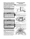
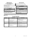
How to Hang
Your Ceiling Fan
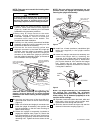
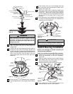
AT LEAST
7'
FLOOR
CEILING
Figure 12
The fan must be hung with at least 7' of clearance
from floor to blades (Figure 12). Do NOT hang this
fan on an 8’ ceiling when using the 12” downrod.
WARNING
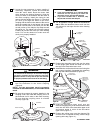
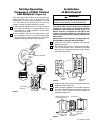
1. Securely attach the hanger bracket to the outlet box
using the two screws supplied with the outlet box
(Figure 13).
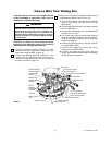
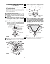
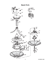
U.L. Model No.: CF820
DECORATIVE
UPPER SCROLL
DOWNROD
CEILING
COVER
SCREW
PIN
HANGER
BALL
SETSCREW
DOWNROD
Figure 11
27. You have now completed the initial assembly of
your new ceiling fan. You can now proceed with
hanging and wiring your fan.
Hanger bracket must seat firmly against outlet box. If
the outlet box is recessed, remove wall board until
bracket contacts box. If bracket and/or outlet box are
not securely attached, the fan could wobble or fall.
WARNING
TWO SCREWS
SUPPLIED WITH
OUTLET BOX
HANGER
BRACKET
TAB
OUTLET
BOX
Figure 13
To reduce the risk of fire, electric shock, or personal
injury, mount fan to outlet box marked “Acceptable
for Fan Support of 50 lbs. or Less”, and use screws
supplied with outlet box. Most outlet boxes
commonly used for support of light fixtures are not
acceptable for fan support and may need to be
replaced. Consult a qualified electrician if in doubt.
WARNING
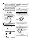
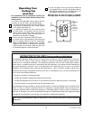
2. Carefully lift the fan and seat the hanger
ball/downrod assembly on the hanger bracket that
was just attached to the outlet box (Figure 14). Be
sure the groove in the ball is lined up with tab on
the hanger bracket (Figure 13).
OUTLET
BOX
HANGER
BRACKET
HANGER BALL/
DOWNROD ASSEMBLY
Figure 14
To avoid possible fire or shock, do not pinch wires
between the hanger ball/downrod assembly and the
hanger bracket.
WARNING
Failure to seat tab in groove could cause damage to
electrical wires and possible shock or fire hazard.
WARNING
25. Reinstall the hanger ball on the downrod
as follows. Route the motor leads through the
hanger ball and slide the hanger ball over the
downrod (Figure 11). Install the pin through the
holes at the top of the downrod and slide the
hanger ball up the downrod, aligning the ball so
the pin is captured in the groove in the top of the
hanger ball. Pull the hanger ball up tight against
the pin and securely tighten the setscrew in the
hanger ball. A loose setscrew could create fan
wobble.
26. The blue, black, white, and yellow leads exiting
the downrod are 80-inches long. Before installing
the fan, measure up approximately 6 to 9-inches
above the ball/downrod assembly. Cut off excess
leads and strip back insulation 1/2-inch from end
of leads.
NOTE: CEILING COVER, SUPPLY WIRES
AND FAN WIRES OMITTED FOR CLARITY.
It is critical that the pin in the hanger ball is properly
installed and the setscrew securely tightened.
Failure to verify that the pin and setscrew are
properly installed could result in the fan falling.
WARNING