


6 U.L. Model No.: CF705
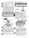
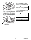
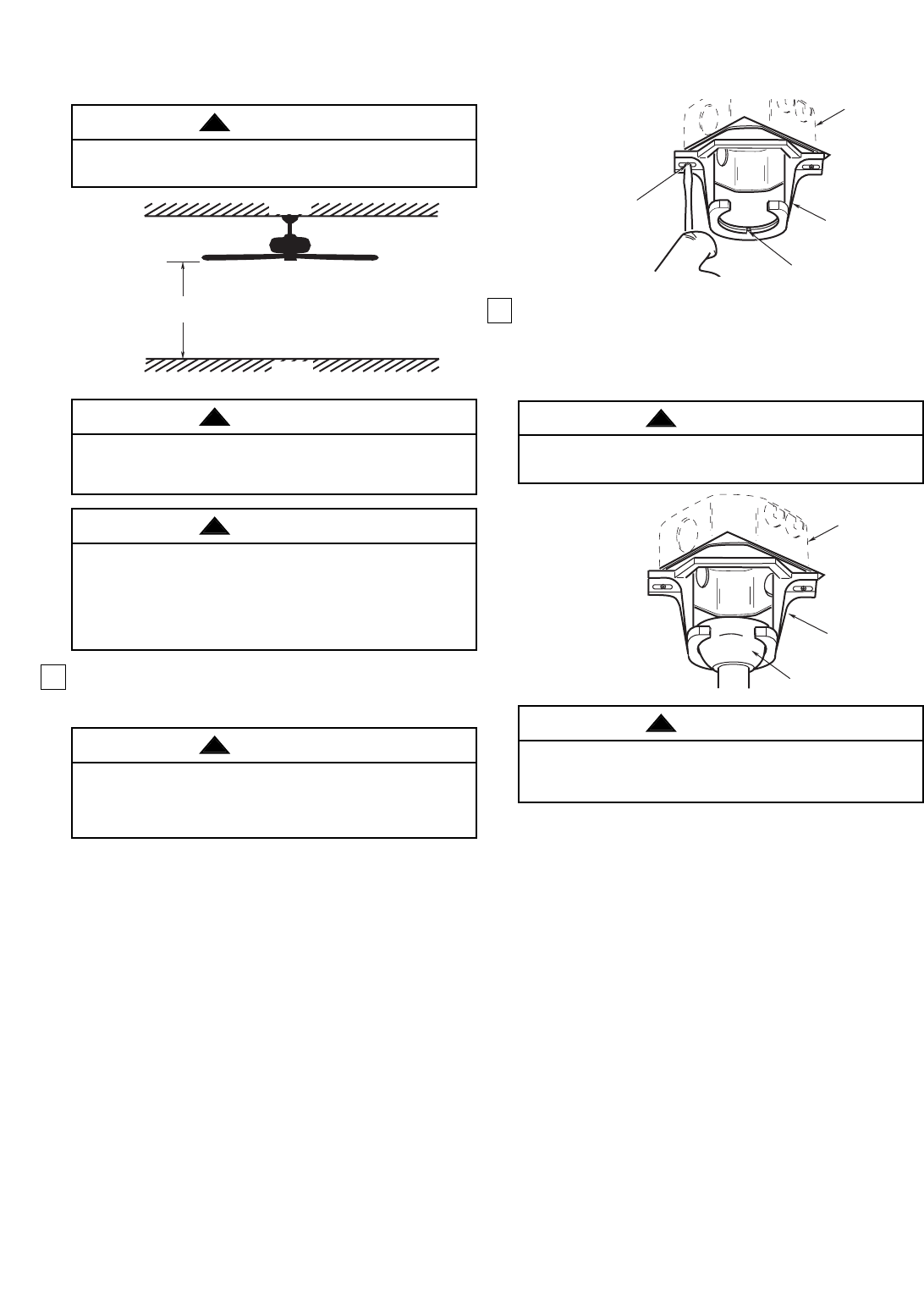
OUTLET
BOX
HANGER
BRACKET
HANGER BALL/
DOWNROD ASSEMBLY
Figure 3
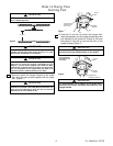
NOTE: CEILINGCOVER,
SUPPLYWIRES AND
FAN WIRESOMITTED
FOR CLARITY.
Figure 8
2. Carefully lift the fan and seat the hanger ball/
downrod assembly on the hanger bracket that was
just attached to the outlet box (Figure 8). Be sure
the groove in the ball is lined up with tab on the
hanger bracket (Figure 7).
Failure to seat tab in groove could cause damage to
electrical wires and possible shock or fire hazard.
WARNING
!
To avoid possible fire or shock, do not pinch wires
between the hanger ball/downrod assembly and
hanger bracket.
WARNING
!
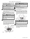
1. Securely attach the hanger bracket to the outlet
box using the two screws supplied with the outlet
box. (Figure 7.)
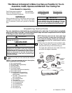
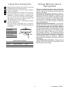
How to Hang Your
Ceiling Fan
AT LEAST
7'
CEILING
FLOOR
Figure 6
TWO SCREWS
SUPPLIED WITH
OUTLET BOX
HANGER
BRACKET
TAB
OUTLET
BOX
Figure 2
Figure 7
The fan must be hung with at least 7' of clearance from
floor to blades (Figure 6).
Hanger bracket must seat firmly against outlet box. If the
outlet box is recessed, remove wall board until bracket con-
tacts box. If bracket and/or outlet box are not securely
attached, the fan could wobble or fall.
WARNING
!
WARNING
!
To reduce the risk of fire, electric shock, or personal injury,
mount fan to outlet box marked “Acceptable for Fan
Support”, and use screws supplied with outlet box. Most
outlet boxes commonly used for support of light fixtures
are not acceptable for fan support and may need to be
replaced. Consult a qualified electrician if in doubt.
WARNING
!
The outlet box and joist must be securely mounted and
capable of supporting at least 50 lbs. Use only a U.L. outlet
box listed as “Acceptable for Fan Support”.
WARNING
!