


5 U.L. Model No.: CF705
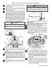
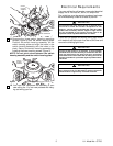
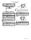
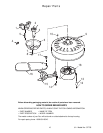
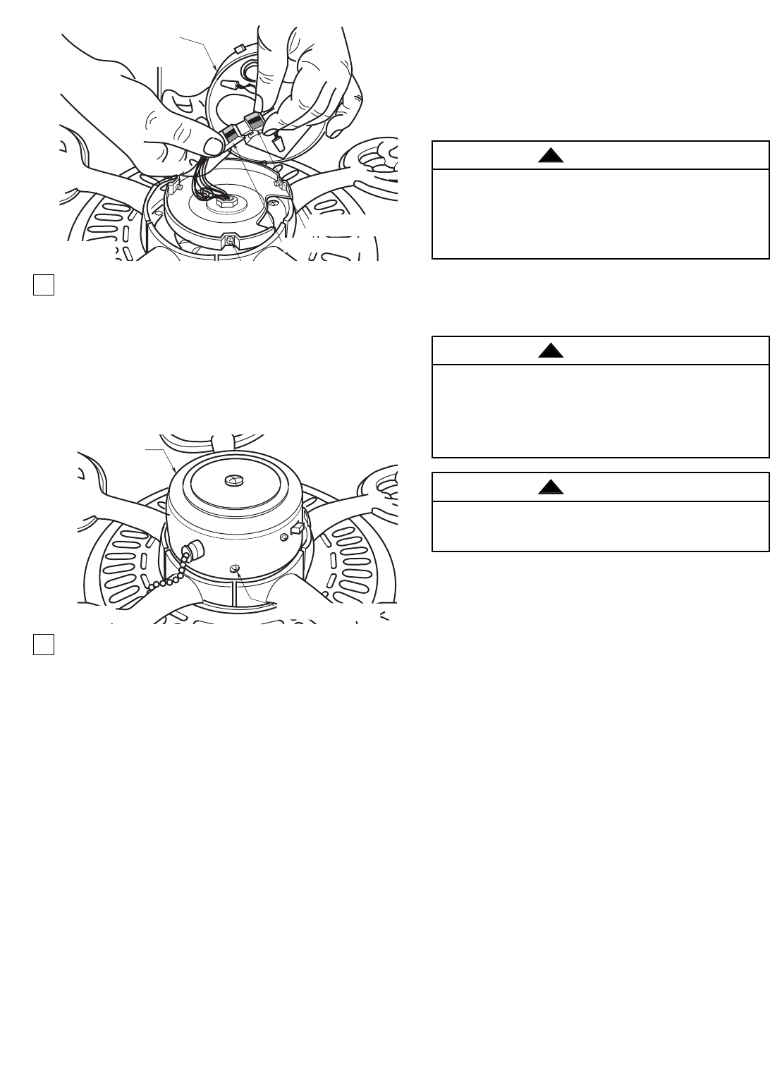
11.Remove the three switch housing mounting
screws (Figure 4) from the switch housing plate.
Position the switch housing assembly on the
switch housing plate and align the holes in the
switch housing assembly with the holes in the
plate. Secure the switch housing assembly by
installing the three mounting screws (Figure 5).
NOTE: Do not pinch wires between the switch
housing assembly and the switch housing plate.
12. You have now completed the assembly of your
new ceiling fan. You can now proceed with hang-
ing and wiring your fan.
MOUNTING SCREWS(3)
SWITCH
HOUSING
ASSEMBLY
Figure 5
SWITCH
HOUSING
ASSEMBLY
SWITCH HOUSING
CONNECTOR
MOTOR CONNECTOR
Figure 4
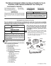
Electrical Requirements
If your fan is to replace an existing ceiling light fixture,
turn electricity off at the main fuse box at this time and
remove the existing light fixture.
Your new ceiling fan will require a grounded electrical
supply line of 120 volts AC, 60 Hz, 15 amp circuit.
The outlet box must be securely anchored and capa-
ble of withstanding a load of at least 50 pounds.
Turning off wall switch is not sufficient. To avoid possible
electrical shock, be sure electricity is turned off at the main
fuse box before wiring. All wiring must be in accordance
with National and Local codes and the ceiling fan must be
properly grounded as a precaution against possible electri-
cal shock.
WARNING
!
To avoid fire or shock, follow all wiring instructions carefully.
Any electrical work not described in these instructions
should be done or approved by a licensed electrician.
WARNING
!
To reduce the risk of fire, electric shock, or personal injury,
mount fan to outlet box marked “Acceptable for Fan
Support”, and use screws supplied with outlet box. Most
outlet boxes commonly used for support of light fixtures
are not acceptable for fan support and may need to be
replaced. Consult a qualified electrician if in doubt.
WARNING
!