


3
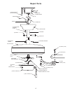
4. The fan is supplied with a hanger ball/downrod
assembly. Slide the downrod (Item 3) into motor mount
adapter until the hole in the downrod aligns with the
cross hole in the adapter. (Make sure wires do not twist
during this step.) Next, insert clevis pin through cross
holes in adapter and downrod. Install hairpin clip in hole
in clevis pin. Now tighten the downrod setscrews
securely to the downrod.
5. To attach switch housing (item 5) align the color stripes
of connectors. Slide the connectors together until plastic
latch on connector snaps over the tab on connector.
Carefully tuck all wires and splices into the switch
housing. Position switch housing (item 5) on plate and
align the holes in the switch housing by installing the
three screws in the side of plate.
NOTE: To install an accessory light kit, remove switch
housing (item 5) and make light kit electrical
connections to blue and white leads marked “For Light”
in the switch housing. Follow light kit instructions for
wiring and installation. Then reinstall switch housing as
outlined above.
6. Lift the fan, without blades, and put the downrod
assembly into the hanger bracket. Make sure to engage
the groove on the hanger ball (item 2) with the tab on the
hanger bracket (item 1) to prevent rotation.
WIRING THE FAN. If you do not have enough
electrical experience, have your fan installed by a
licensed electrician.
NOTE: This fan comes with 80” long electrical leads.
Before installing the fan, measure approximately 6 to 9
inches above the hanger ball/downrod assembly. Cut
off excess leads and strip back insulation 1/2-inch from
end of leads.
General
After opening the box you should find the following parts:
• One motor housing assembly
• One upper canopy
• One set of blade flanges
• One hanger bracket
• One downrod/hanger ball assembly
• Parts bag
• One set of blades
• One switch housing cover
• One Owner's Manual
Installation Instructions
The fan must be hung with at least 7' of clearance
from floor to blades.
1. If your fan is to replace an existing ceiling light fix-
tures, turn electricity off at the main fuse box at this
time and remove the existing light fixture.
Turning off wall switch is not sufficient. To avoid
possible electrical shock, be sure electricity is
turned off at the main fuse box before wiring. All
wiring must be in accordance with National and
Local Codes and the ceiling fan must be properly
grounded as a precaution against possible electrical
shock.
To reduce the risk of fire, electrical shock, or personal
injury, mount fan to outlet box marked “Acceptable for
Fan Support”, and use screws supplied with outlet box.
Most outlet boxes commonly used for support of light
fixtures are not acceptable for fan support and may
need to be replaced. Consult a qualified electrician if
in doubt.
It is critical that the clevis pin in the motor mount
adapter is properly installed and the setscrews securely
tightened. Failure to verify that the clevis pin and
setscrews are properly installed could result in the fan
falling.
The outlet box and joist must be securely mounted and
capable of supporting at least 50 lbs. Use only a U.L.
outlet box listed as “Acceptable for Fan Support”.
Turning off wall switch is not sufficient. To avoid
possible electrical shock, be sure electricity is
turned off at the main fuse box before wiring. All
wiring must be in accordance with National and
Local codes and the ceiling fan must be properly
grounded as a precaution against possible electrical
shock.
2. Install hanger bracket (item 1) to outlet box using the two
screws supplied with the outlet box. Hanger bracket must
seat firmly against outlet box. Remove wall board if
necessary until bracket contacts box.
3. Run the downrod (item 3) through the ceiling cover
(item 4). Run the three wires from the fan through the
downrod.
WARNING
!
WARNING
!
WARNING
!
WARNING
!
WARNING
!
WARNING
!
Hanger bracket must seat firmly against outlet box. If
the outlet box is recessed, remove wall board until
bracket contacts box. If bracket and/or outlet box are
not securely attached, the fan could wobble or fall.
WARNING
!
Failure to seat tab in groove could cause damage to
electrical wires and possible shock or fire hazard.
WARNING
!
To avoid possible fire or shock, do not pinch wires
between the hanger ball/downrod assembly and
hanger bracket.
WARNING
!