


4
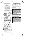
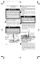
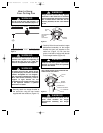
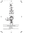
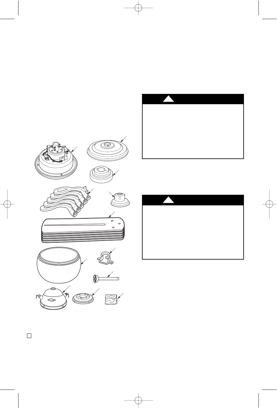
l. One loose parts bag containing:
1. Two 8-32 x 1-1/4” threaded studs
2. Two knurled knobs
3. Two lockwashers
4. Five wire connectors
5. One clevis pin/hairpin clip
assembly
6. Eleven 1/4-20 x 1/2” oval
head screws
7. Sixteen 10-32 x .30” pan
head screws
8. Sixteen #10 flat washers
9. Four 8-32 x 1/4” pan head screws
10. One pendant (large)
11. One pendant (small)
12. Two chain couplings
NOTE: Place the parts from the loose
parts bags in a small container to keep
them from being lost.
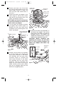
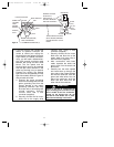
2. Remove the fan motor and housing
assembly from the protective plastic
bag. Place the fan assembly into the
lower foam pad with the bottom of the
motor facing up.
The lower foam pad serves as a holder
for the fan during the first stages of
assembly.
C
E
F
K
A
D
B
G
H
I
J
L
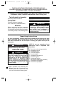
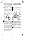
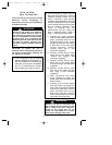
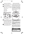
Your new ceiling fan will require a
grounded electrical supply line of 120 volts
AC, 60 Hz, 15 amp circuit.
The outlet box must be securely anchored
and capable of withstanding a load of at
least 50 pounds.
To reduce the risk of fire, electric shock,
or personal injury, mount fan to outlet box
marked “Acceptable for Fan Support”,
and use screws supplied with outlet box.
Most outlet boxes commonly used for
support of light fixtures are not
acceptable for fan support and may need
to be replaced. Consult a qualified
electrician if in doubt.
!
WARNING
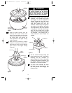
If your fan is to replace an existing ceiling
light fixture, turn electricity off at the main
fuse or circuit breaker box at this time and
remove the existing light fixture.
Electrical Requirements
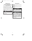
Turning off wall switch is not sufficient.
To avoid possible electrical shock, be
sure electricity is turned off at the main
fuse or circuit breaker box before wiring.
All wiring must be in accordance with
National and Local codes and the ceiling
fan must be properly grounded as a
precaution against possible electrical
shock.
!
WARNING
BP7305 Westfield 6/30/06 12:10 AM Page 4