


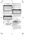
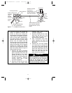
6. Remove and retain one of the three
pan head screw/lockwashers from the
motor flange (Figure 2); loosen the
other two pan head screws three or
four turns.
7. Position the switch cup adapter on the
motor flange so that the two screws
mate with the two keyhole slots in the
switch cup adapter (Figure 2).
NOTE: Make sure that the lockwashers
are positioned between the screw head
and the switch cup adapter.
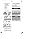
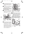
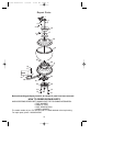
8. Turn the switch cup adapter clockwise
and tighten both screws (Figure 3).
Reinstall the other pan head screw/
lockwasher in the remaining hole in the
switch cup adapter.
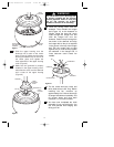
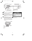
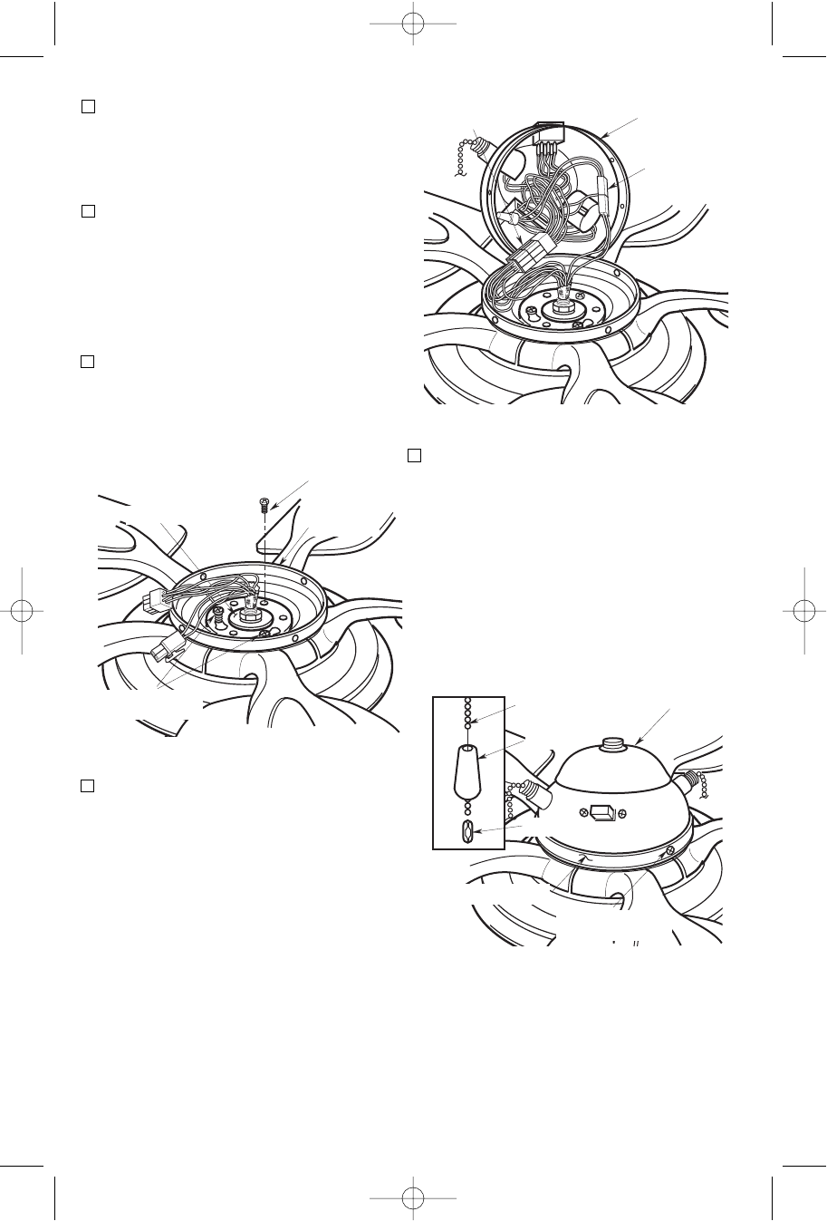
9. Carefully rest the switch cup assembly
on the fan blades, then engage the
large (9-pin) connector of the switch
cup assembly with the large motor
connector (Figure 4). Connect the
small (2-pin) connector of the switch
cup assembly with the small motor
connector. The two connectors are
keyed and color-coded and must be
mated correctly (color-to-color) before
they can be engaged. Make sure the
latches are engaged properly.
6
MOTOR FLANGE
SWITCH CUP
ADAPTER
TIGHTEN TWO PAN
HEAD SCREWS
INSTALL ONE PAN HEAD
SCREW/LOCKWASHER
Figure 3
SWITCH CUP
ASSEMBLY
SMALL (2-PIN)
CONNECTORS
LARGE (9-PIN)
CONNECTORS
Figure 4
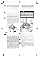
10. Position the switch cup assembly on
the switch cup adapter. Line up the
three holes in the switch cup with the
threaded holes in the switch cup
adapter and install four 8-32 x 1/4” pan
head screws (supplied) (Figure 5).
CAUTION: Before installing and
tightening the screws, be sure there
are no wires pinched between the
switch cup adapter and switch cup
assembly.
SWITCH CUP
ASSEMBLY
PULL CHAIN
8-32 x 1/4" PAN HEAD
SCREW (4)
SWITCH CUP ADAPTER
PENDANT
COUPLING
Figure 5
BP7305 Westfield 6/30/06 12:10 AM Page 6