


13
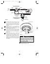
Setting Operating
Frequency of Wall
Control and Receiver
(Figure 17)
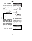
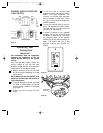
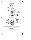
Your wall control and receiver have code
switches which must be set in one of 16
possible code combinations. The four
levers (numbered 1, 2, 3, and 4) on the
switches are factory-set in the ON (up)
position. Change the switch settings as
follows:
1. Slide the four switch levers in the wall
control to your choice of ON (up) or
down positions. Use a ball-point pen or
small screwdriver and slide the levers
firmly up or down.
2. In the receiver, slide the four switch
levers to the same positions as set in
the wall control. Make sure the levers
on both switches are in the same
positions, otherwise the fan will not
operate.
Figure 17
WALL CONTROL
LEVERS
ON
1
234
RECEIVER
SWITCH LEVERS
ON
1
234
CODE
SWITCH
ANTENNA WIRE
1 2 3 4
ON
RECEIVER
CODE
SWITCH
WALL
CONTROL
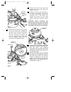
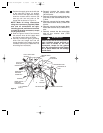
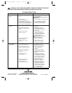
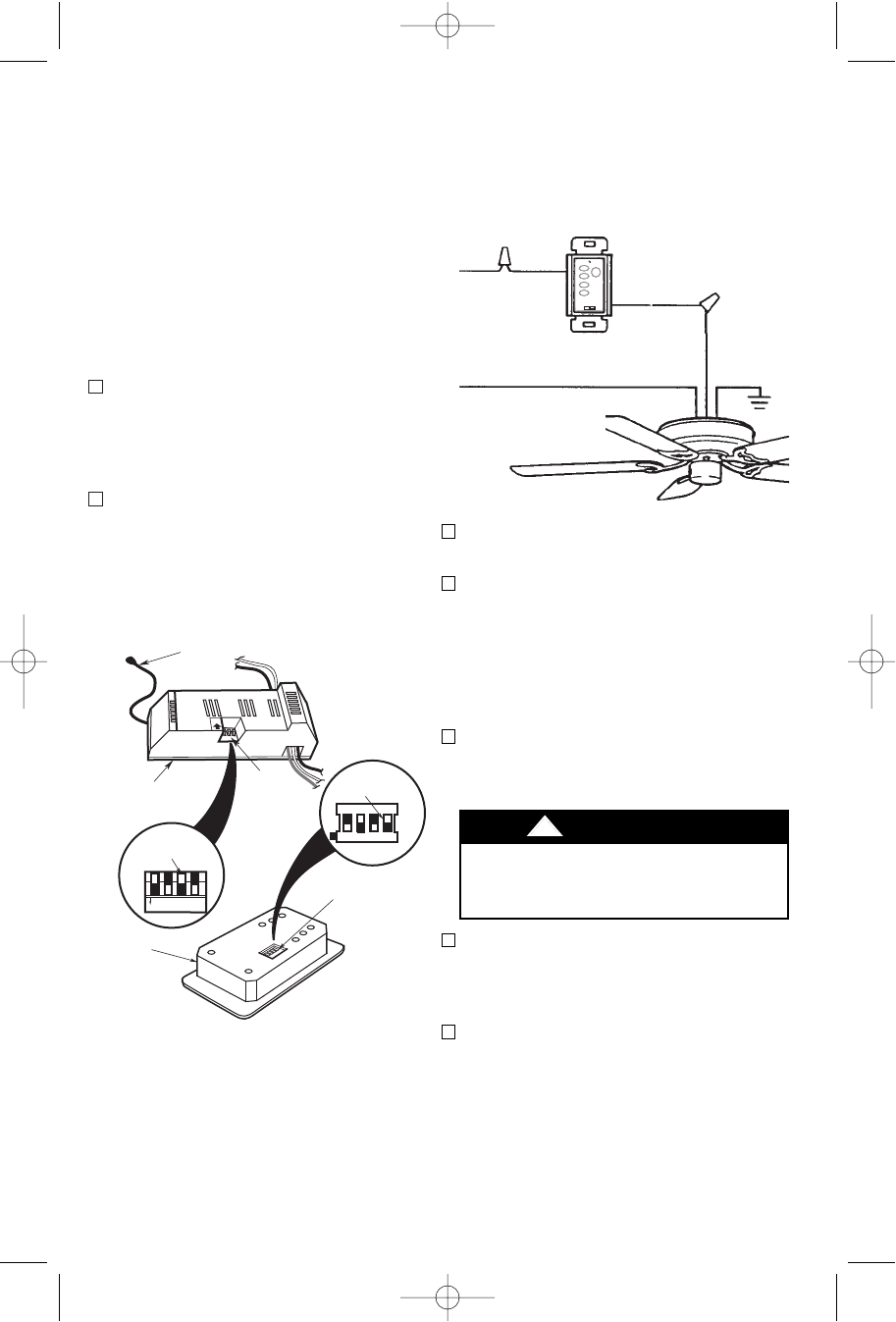
Installation of Wall
Control
SINGLE-POLE INSTALLATION
(Figure 18)
1. Disconnect power at circuit breaker or
remove fuse.
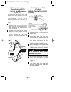
2. Remove faceplate and screws from
existing wall control. Pull control out
from the wall box. Determine the “hot”
wire and the “load” wire and disconnect
these wires from control. Do not
attempt to disconnect any wires not
already connected to existing control.
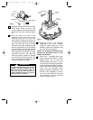
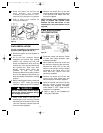
3. Before installing wall control, place wall
control in “OFF” mode by pushing
“ON/OFF” switch to the “OFF” position.
4. Connect one black wire of wall control
to the “hot” wire. Securely connect
wires with wire connectors supplied
(Figure 19).
5. Connect one black wire of wall switch
to the “load” (black) wire in wall box.
Securely connect wires with wire
connector supplied.
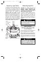
EMERSON
®
HI
MED
LOW
FAN OFF
LIGHT
ONOFF
FAN/LIGHT
WALL CONTROL
HOT BLK
NEUTRAL
BLACK
GROUND
LOAD
BLACK
REMOTE CONTROL
RECEIVER LOCATED
WITHIN THE CEILING
COVER
Figure 18
Do not connect any neutral (white)
wire to this control. Incorrect wiring
will damage this control.
!
WARNING
BP7306 Nottingham 6/19/06 1:00 PM Page 13