


8
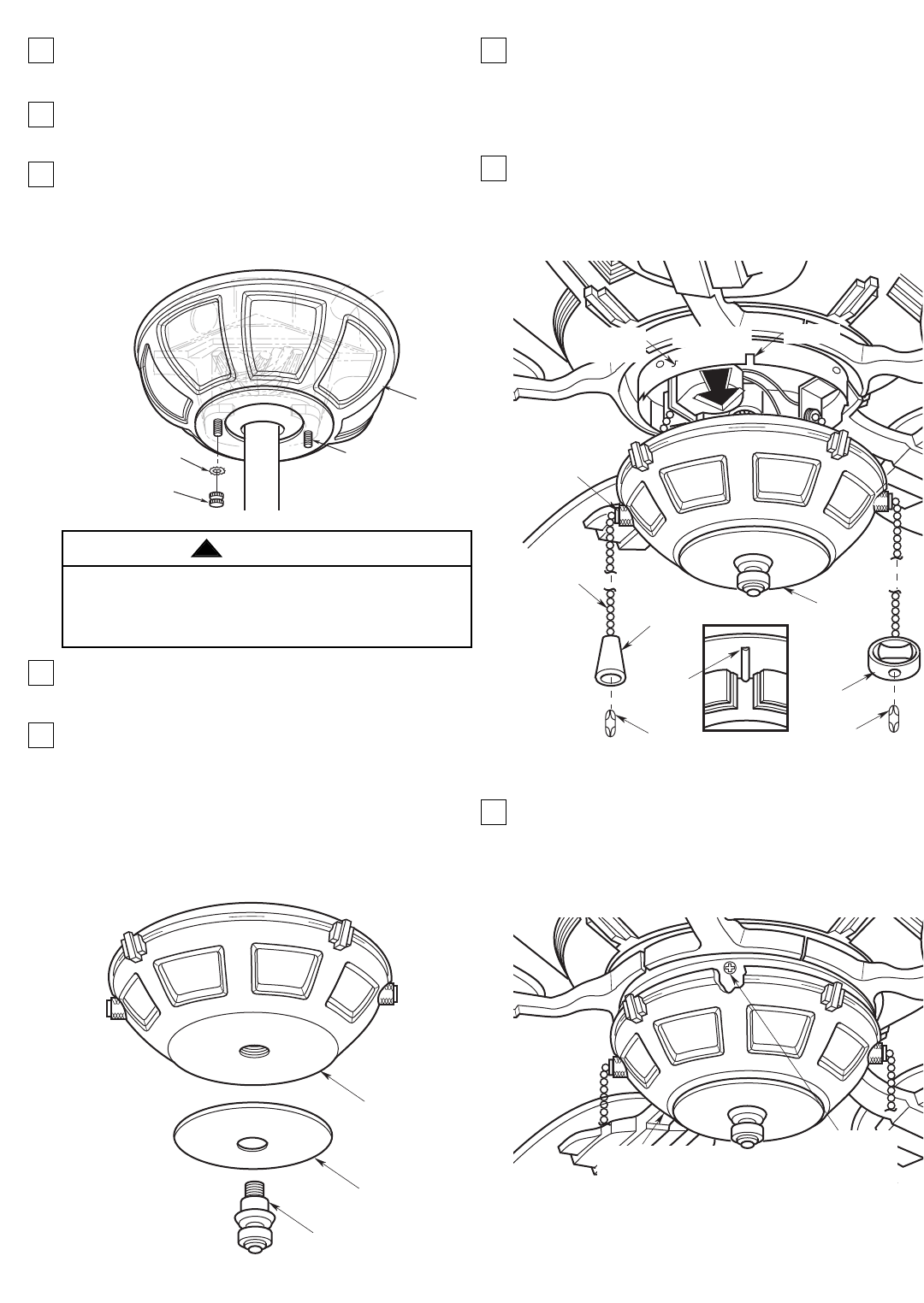
4. Screw the two 1-1/4” threaded studs (supplied) into
the tapped holes in the hanger bracket
(Figure 9).
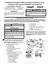
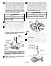
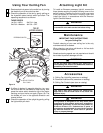
5. Lift the ceiling cover up to the threaded studs and
turn until the studs protrude through the holes in
the ceiling cover (Figure 12).
6. Secure the ceiling cover in place by sliding
lockwashers (supplied) over the threaded studs
and installing the two knurled knobs (supplied).
(Figure 12.) Tighten the knurled knobs securely
until the ceiling cover fits snugly against the ceiling.
7. Screw in four T8 25-watt (maximum) candelabra
base bulbs (supplied) into the uplight sockets on
top of the fan housing assembly.
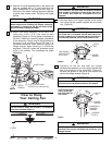
8. Position the cover plate on the switch housing
cover (Figure 13) and secure in place by installing
the finial nut finger tight.
NOTE: If you are going to install an Emerson
accessory light kit, do not install the finial nut and
cover plate. Instead, install the switch housing
cover on the light kit in accordance with the
Emerson light kit Owner’s Manual.
To avoid possible fire or shock, make sure that the
electrical wires are completely inside the outlet box
and not pinched between the ceiling cover and the
ceiling.
WARNING
!
CEILING
COVER
THREADED
STUDS (2)
KNURLED
KNOB (2)
LOCKWASHER (2)
Figure 12
SWITCH
HOUSING
COVER
COVER PLATE
FINIAL NUT
Figure 13
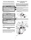
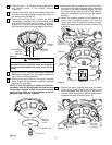
8-32 x 3/8"
PAN HEAD
SCREWS (3)
SWITCH HOUSING
COVER
Figure 15
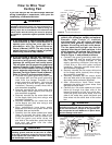
9. Position the switch housing cover so that the tab on
the inside of the switch housing cover aligns with
the notch in the switch housing (Figure 14). With
the switch housing cover held in this position,
pass the shortest pull chain through the nearest
bushing.
10. Attach the smaller pendant to the smallest pull
chain using a coupling (Figure 14). Pass the
longer pull chain through the other bushing;
attach the largest pendant to this pull chain using
a coupling.
11. Position the switch housing cover over the switch
housing and rotate slightly until the tab in the
cover engages with the notch in the switch
housing. Install three 8-32 x 3/8” pan head screws
to secure the cover in place (Figure 15).
SWITCH
HOUSING
COVER
PENDANT
COUPLING
TAB
PENDANT
COUPLING
VIEW "A"
BUSHING
SWITCH
CHAIN
SWITCH
HOUSING
NOTCH
SEE VIEW
"A"
Figure 14