


11. Use the 10 round recessed holes in the motor hub
that are marked with a “5” and install the five
blade assemblies in accordance with Step 12.
One side of the switch housing has been indented
to allow easy access when installing the flange
screws.
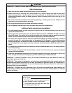
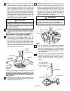
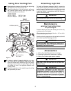
12. Attach one blade assembly to the motor hub
using two 10-32 x 5/8” oval head screws
(supplied) (Figure 6). Do not tighten completely at
this time. Install four remaining blade assemblies
in the same way. Gently snug all flange screws to
the motor hub, working around the hub in a
clockwise sequence. Next, securely tighten all
flange screws, again working in a clockwise
sequence. Failure to follow this procedure could
result in fan wobble. This completes the blade
installation.
6
BLADE FLANGE
5
5
4
MOTOR
HUB
SWITCH
HOUSING
10-32 x 5/8" OVAL HEAD
SCREWS (2 per blade assmebly)
Figure 6
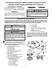
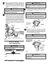
How to Hang
Your Ceiling Fan
CEILING
FLOOR
AT LEAST
7'
Figure 7
The fan must be hung with at least 7' of clearance
from floor to blades (Figure 7).
WARNING
!
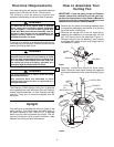
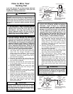
TWO SCREWS
SUPPLIED WITH
OUTLET BOX
HANGER
BRACKET
TAB
OUTLET
BOX
Figure 8
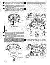
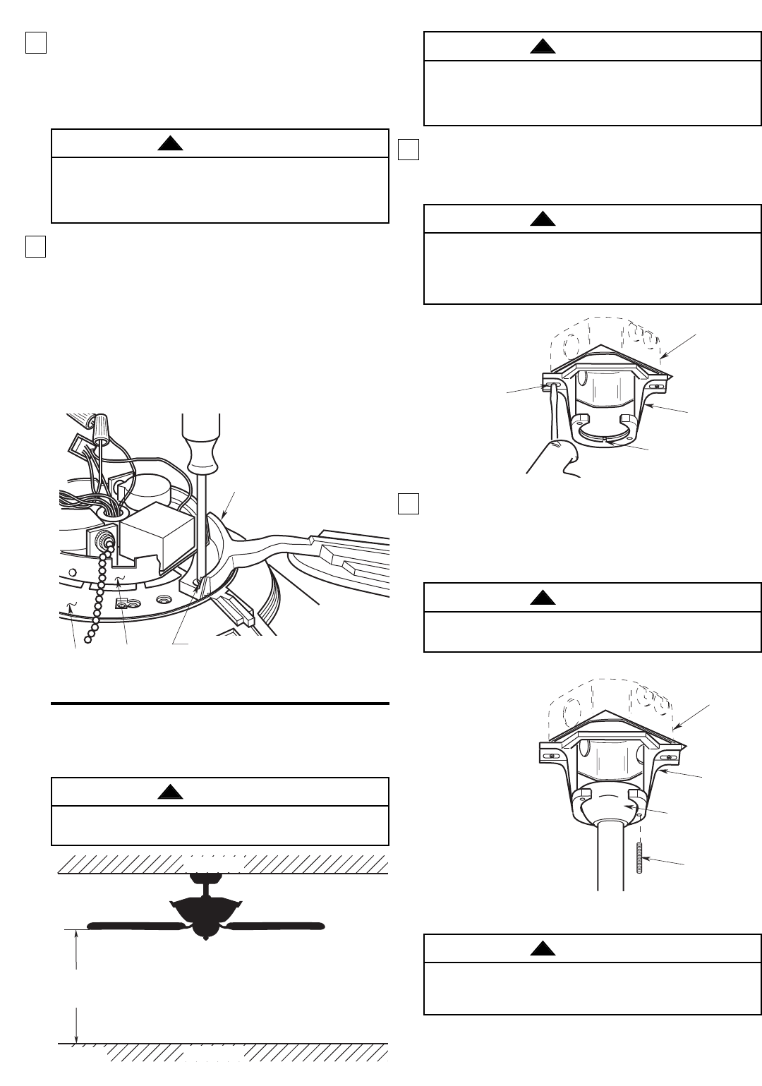
2. Carefully lift the fan and seat the hanger
ball/downrod assembly on the hanger bracket that
was just attached to the outlet box (Figure 9).
Be sure the groove in the ball is lined up with the
tab on the hanger bracket (Figure 8).
The outlet box and joist must be securely mounted
and capable of supporting at least 50 lbs. Use only a
U.L. outlet box listed as “Acceptable for Fan
Support”.
WARNING
!
To reduce the risk of personal injury, do not bend the
blade flanges when installing the flanges, balancing
the blades, or cleaning the fan. Do not insert foreign
objects between rotating fan blades.
WARNING
!
Failure to seat tab in groove could cause damage to
electrical wires and possible shock or fire hazard.
WARNING
!
Hanger bracket must seat firmly against outlet box. If
the outlet box is recessed, remove wall board until
bracket contacts box. If bracket and/or outlet box are
not securely attached, the fan could wobble or fall.
WARNING
!
1. Securely attach the hanger bracket to the outlet
box using the two screws supplied with the outlet
box. (Figure 8.)
OUTLET
BOX
HANGER
BRACKET
HANGER BALL/
DOWNROD
ASSEMBLY
NOTE: CEILING COVER,
SUPPLY WIRES AND
FAN WIRES OMITTED
FOR CLARITY.
THREADED
STUD (2)
Figure 9
To avoid possible fire or shock, do not pinch wires
between the hanger ball/downrod assembly and
hanger bracket.
WARNING
!