


5
9. The fan comes with blue, black and white leads
that are 80” long. Before installing fan, measure up
approximately 6 to 9-inches above the ball/
downrod assembly. Cut off excess leads and strip
back insulation 1/2-inch from end of leads.
Electrical Requirements
Your new ceiling fan will require a grounded electrical
supply line of 120 volts AC, 60 Hz, 15 amp circuit.
The outlet box must be securely anchored and
capable of withstanding a load of at least 50 pounds.
If your fan is to replace an existing ceiling light fixture,
turn electricity off at the main fuse box at this time and
remove the existing light fixture.
How to Hang Your
Ceiling Fan
It is critical that the pin in the hanger ball is properly
installed and the setscrew securely tightened.
Failure to verify that the pin and setscrew are
properly installed could result in the fan falling.
WARNING
!
To reduce the risk of fire, electric shock, or personal
injury, mount fan to outlet box marked acceptable for
fan support, and use screws supplied with outlet
box. Most outlet boxes commonly used for support
of light fixtures are not acceptable for fan support
and may need to be replaced. Consult a qualified
electrician if in doubt.
WARNING
!
Turning off wall switch is not sufficient. To avoid pos-
sible electrical shock, be sure electricity is turned off
at the main fuse box before wiring. All wiring must be
in accordance with national and local codes and the
ceiling fan must be properly grounded as a precaution
against possible electrical shock.
WARNING
!
The outlet box must be securely anchored and capable
of withstanding a load of at least 50 lbs.
WARNING
!
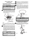
AT LEAST
7'
CEILING
FLOOR
Figure 6
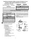
The fan must be hung with at least 7' of clearance
from floor to blades (Figure 6).
WARNING
!
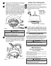
1. Securely attach the hanger bracket to the outlet
box using the two screws supplied with the outlet
box. (Figure 7).
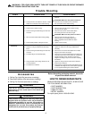
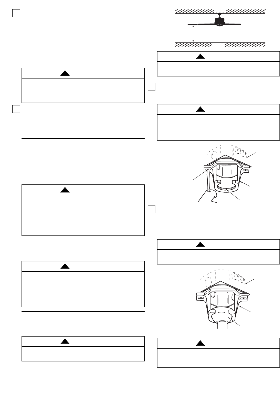
2. Carefully lift the fan and seat the hanger ball/
downrod assembly on the hanger bracket that was
just attached to the outlet box (Figure 8). Be sure
the groove in the ball is lined up with tab on the
hanger bracket (Figure 7).
Hanger bracket must seat firmly against outlet box. If
the outlet box is recessed, remove wall board until
bracket contacts box. If bracket and/or outlet box are
not securely attached, the fan could wobble or fall.
WARNING
!
TWO SCREWS
SUPPLIED WITH
OUTLET BOX
HANGER
BRACKET
TAB
OUTLET
BOX
Figure 2
Figure 7
Failure to seat tab in groove could cause damage to
electrical wires and possible shock or fire hazard.
WARNING
!
OUTLET
BOX
HANGER
BRACKET
HANGER BALL/
DOWNROD ASSEMBLY
Figure 3
NOTE: CEILING COVER,
SUPPLY WIRES AND
FAN WIRES OMITTED
FOR CLARITY.
Figure 8
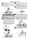
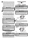
8.Reinstall the hanger ball on the downrod (Figure 5)
as follows. Route the motor leads through the hanger
ball and slide the hanger ball over the downrod.
Install the pin through the holes at the top of the
downrod and slide the hanger ball up the downrod,
aligning the ball so the pin is captured in the groove
in the top of the hanger ball. Pull the hanger ball up
tight against the pin and securely tighten the setscrew
in the hanger ball. A loose setscrew could create fan
wobble.
NOTE: For ease of installation, first the fan motor
and housing assembly is installed on the ceiling.
Then after wiring of the fan is completed, the fan
blade assemblies will be attached to the motor hub.
To avoid possible fire or shock, do not pinch wires
between the hanger ball/downrod assembly and the
hanger bracket.
WARNING
!