www.white-rodgers.com
264
TECHNICAL HELP
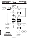
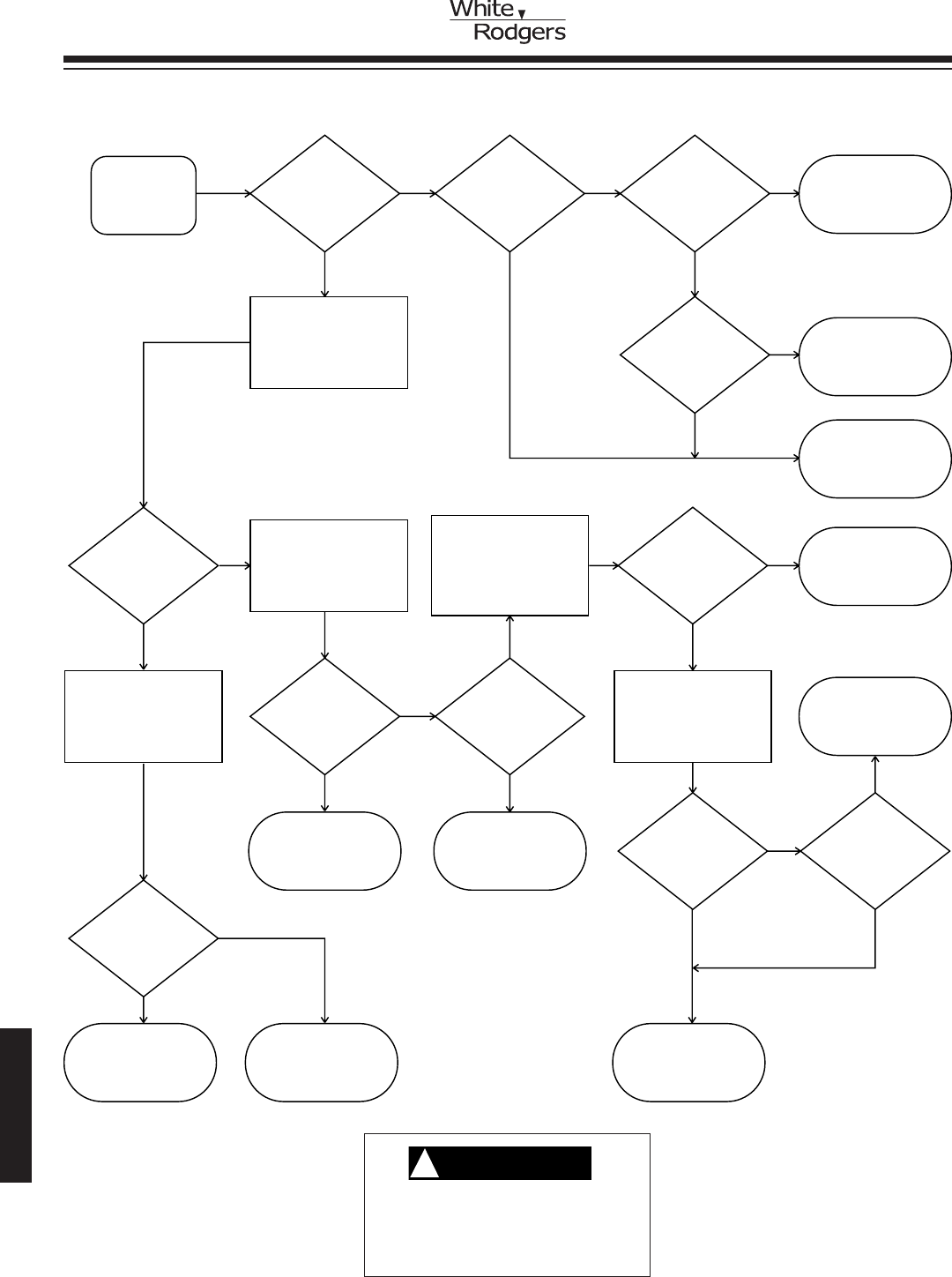
Flame
Sensor
Check
Does main
burner remain
lit?
YES NO
YESNO
Is blower
at heat speed
within 1 minute
of burner ignition?
Does ignitor remain
energized with
flame present?
De-energize system.
Disconnect 12-pin
connector. Connect
ohmmeter from flame
sensor pin FP to
burner GROUND.
Replace sensor.
Energize system.
Check operation.
NO
Replace control.
Check operation.
YES
5A 5C5B
5E
5G
Disconnect flame
sensor from wire.
Measure continuity from
wire end to FP pin
on 12-pin connector.
5I
Disconnect AC power to
system at main fuse or
circuit breaker. Connect
voltmeter from control
terminal LINE NEUTRAL
to BURNER GROUND.
Energize module.
5L
NO
NO
Is 120V
present at
control terminals
HEAT & CIR
NEUTRAL?
5D
5K
5O
5H
YES
YES
Is resistance
less than
50 megohms?
Is 1 microamp
or more
present?
Replace flame
sensor lead. Check
operation.
NO
YES
NO
Replace control
module. Check
operation.
Clean surface of
flame sensor with
fine steel wool.
Reinstall. Check
operation.
Reverse 120V
LINE & NEUTRAL
wires. Energize
system. Check
operation.
Repair or
replace wire.
Energize system.
Check operation.
Connect ground
wire from burner to
12-pin connector
terminal GROUND.
Check operation.
NO
YES
YES
YES
Is
control
ground wire
connected to
burner
ground?
5J
NO NO
Is sensor
lead good?
Disconnect lead
from flame sensor.
Connect ohmmeter
from sensor to
burner ground.
5N
Connect a microammeter
in series with flame
sensor and sensor
lead. Energize system.
Measure current when
burner ignites.
5F
Is resistance
less than
50 megohms
(50,000,000
Ohms)?
5M
Is 120V
present at
burner ground?
NO
5P
Remove
sensor.
Does sensor
have carbon or
dust buildup?
YES
Repair wiring
and/or replace
indoor blower
motor. Check
operation.
System is
functioning
properly.
YES
CHART 5
WARNING
!
If diagnostic indicator (LED)
shows continuous flashing, turn
off gas supply at source before
disconnecting electrical power!
INTEGRATED FURNACE
CONTROL MODULE
TROUBLESHOOTING
GUIDE


