www.white-rodgers.com
263
TECHNICAL HELP
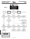
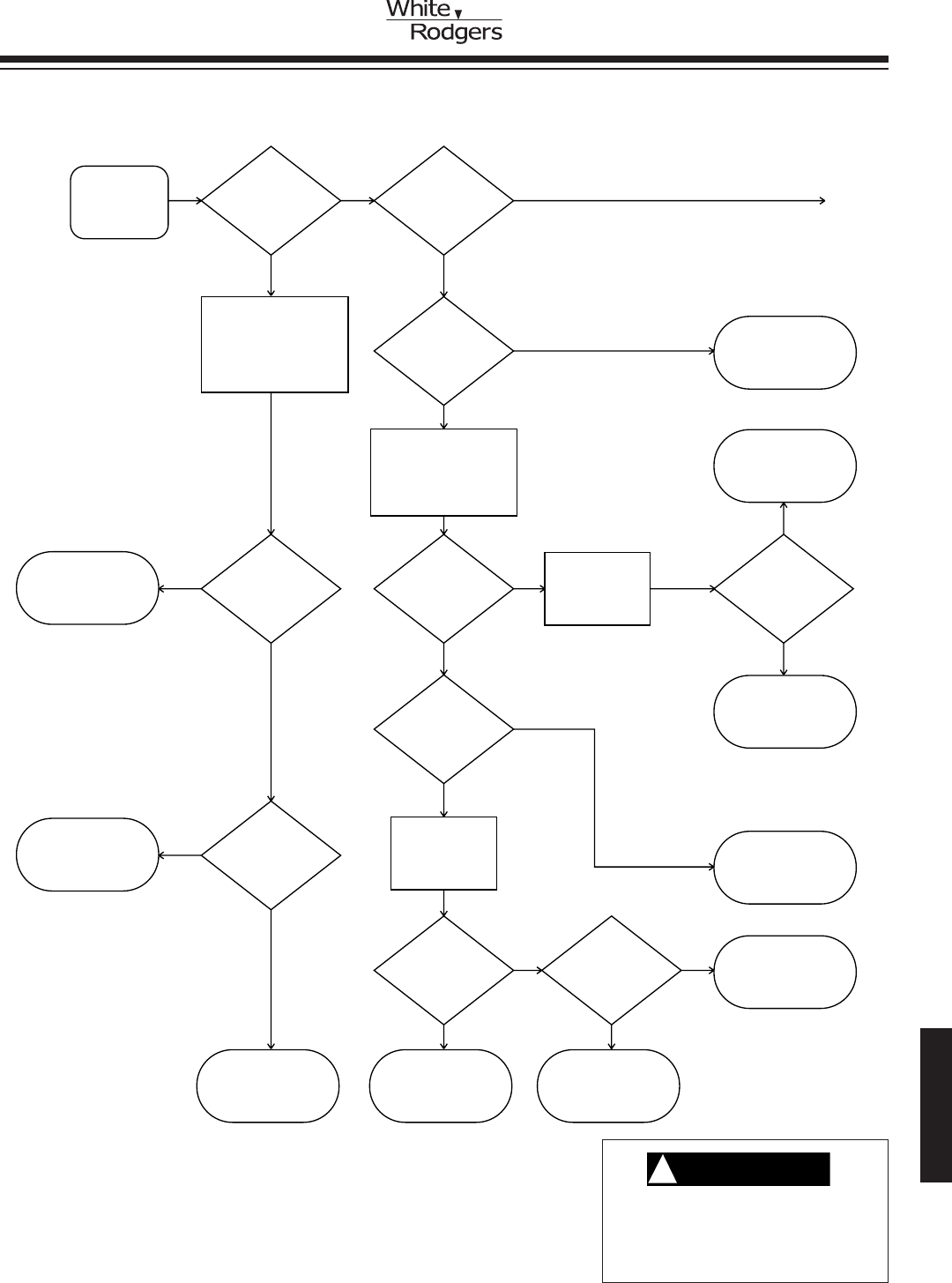
Main Burner
Ignition Check.
Inducer ON.
Does ignitor
warm up and
glow?
YES YES
NONO
Does burner
ignite?
Turn power OFF to furnace.
Unplug ignitor from wire
harness. Connect voltmeter
across ignitor wiring
harness leads from
control. Energize
system.
Turn manual knob to
OFF position. Connect
manometer to outlet
pressure tap. Turn knob
to ON position.
Energize system.
Is 120V
present at
control terminals
IGN & IGN
NEUTRAL?
Replace control
module. Check
operation.
Replace gas
valve. Energize
system. Check
operation.
NO
YES
NO
Repair or
replace broken
leads to gas valve.
Check operation.
4A 4E
4B
YES
Is gas
valve manual
knob in ON
position?
4F
4C
4G
4H
4K
4N
4I
4L
4M
YES
YES
Is 24V
detected
across gas
valve leads after
ignitor warm-
up time?
Is 24V
present
across control
MV terminals after
ignitor warm-
up time?
Replace control.
Check operation.
NO
YES
NO
Purge system of
air. Energize
system. Check
operation.
Adjust manifold
to required
pressure setting.
Check operation.
Restore gas
supply at source.
Check operation.
Replace ignitor.
Check operation.
Replace broken or
defective wiring.
Check operation.
NO NO
YES
Is outlet
pressure
detected after
ignitor warm-
up time?
YES
Is gas at
source?
Is 120V
present at
ignitor leads?
4D
4J
Is manifold
pressure
adjusted to
required
setting?
YES
NO
Turn manual knob
to ON position.
Check operation.
NO
Refer to service
facts or installer’s
guide for proper
pressure settings.
Connect voltmeter
to gas valve
leads. Energize
system.
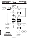
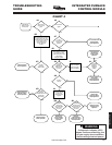
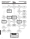
CHART 4
WARNING
!
If diagnostic indicator (LED)
shows continuous flashing, turn
off gas supply at source before
disconnecting electrical power!
INTEGRATED FURNACE
CONTROL MODULE
TROUBLESHOOTING
GUIDE


