9
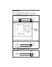
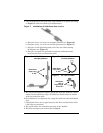
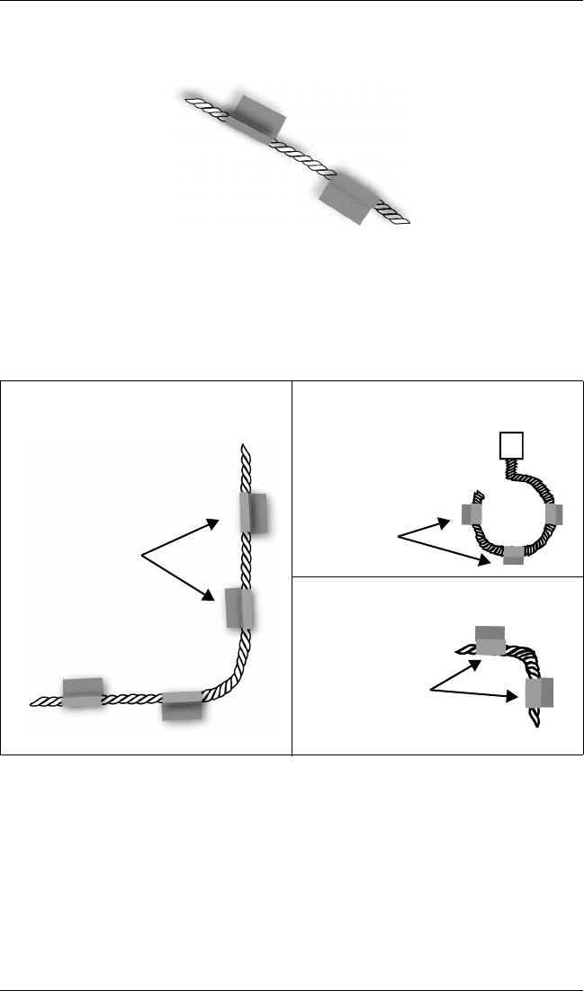
4. The installation of the hold-down clips should be in pairs according
to Figure 5 with the following considerations:
Figure 5 Installation of hold-down clips in pairs
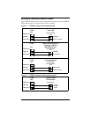
a. One pair every 6 to 8 feet in straight patterns (see Figure 6).
b. One pair every 3 to 4 feet in circular patterns (see Figure 7).
c. One pair at the beginning and end of the arc when turning
90 degrees (see Figure 8).
d. One pair as needed to maintain consistent uniform contact
between the floor and detection cable.
5. Be certain the detection cable is protected from the adhesive instal-
lation for the hold-down clips. No adhesive should come in contact
with the detection cable.
6. Once adhesive is completely dry, snap the cable into each hold-down
clip.
7. Check that there are no gaps between the floor and detection cable.
(Add clips as required.)
8. Be certain there are no alarms present on the module.
9. Do final testing as per instruction in Step 2.
Figure 6 Cable laid in
straight patterns
Figure 7 Cable laid in
circular patterns
Figure 8 90° turn in cable
Hold-down
clips every
6-8 ft.
Hold-down
clips every
3-4 ft.
Hold-down
clips at
beginning &
end of arc


