4
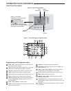
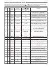
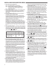
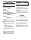
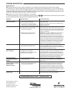
Programming and Confi guration Items
1
“Heat" “A/C” “Off” identifi es button. When fi lled indi-
cates system mode selected.
2
"Aux" inidicates thermostat confi gured for Heat Pump.
When fi lled indicates Auxiliary stage is operating.
3
"Adv Day" identifi es button when in schedule mode.
4
"Time" identifi es button when in schedule mode.
5
"Fan" identifi es button. When fi lled indicates Fan is on.
6
"Run" identifi es button to begin normal operation.
7
"Sched" identifi es button to be used during program-
ming or "Run Sched" identifi es button to return to
normal operation.
8
"Hold" "Copy" "Menu" identifi es button.
9
"Limit" indicates temperature is adjusted to the limit set
in the confi guration menu.
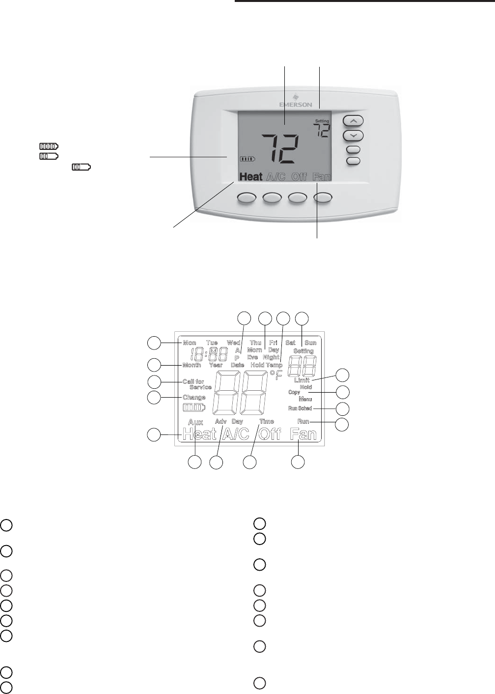
THERMOSTAT QUICK REFERENCE
Home Screen Description
Figure 6 – Home Screen Display
Figure 7 – Programming & Confi guration Items
10
"Setting" indicates the setpoint temperature.
11
"Hold Temp" indicates temporary hold or "Hold" indi-
cates hold mode.
12
"Morn" "Day" "Eve" "Night" indicates period being
programmed or current program in Run mode.
13
"A" "P" indicates time as Morning (A) or Evening (P).
14
"Mon - Sun" indicates day of week.
15
"Month" "Year" "Date" indicates the Month Year or
Date when setting time.
16
"Call For Service" indicates a diagnostic fault in the
heating/cooling system. It does not inidicate a fault in the
thermostat.
17
"Change" indicates when batteries are low and should
be replaced.
7
6
4
1
3
17
16
15
13
12
10
8
9
2 5
14
11
Room
Temperature
Setting
Temperature
System
Indicators
Fan
Indicator
Battery Level Indicator
Indicating the current power level
of the 2 “AA” batteries.
Full power remaining.
Half power remaining.
Change The batteries should
be replaced at this time with 2 new
premium brand “AA” Alkaline batteries.
(See page 2 for more details).


