


WIRING DIAWIRING DIA
WIRING DIAWIRING DIA
WIRING DIA
GRAMSGRAMS
GRAMSGRAMS
GRAMS
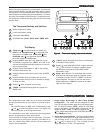
Refer to equipment manufacturers' instructions for specific
system wiring information.
You can configure the thermostat for use with the following
heat pump system types:
HEAT PUMP TYPE 1. Single stage compressor system; gas
or electric backup.
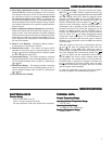
This thermostat is designed to operate a single-transformer
system. If you have a two-transformer system, cut and tape off
Heat Pump Terminal OutputsHeat Pump Terminal Outputs
Heat Pump Terminal OutputsHeat Pump Terminal Outputs
Heat Pump Terminal Outputs
one transformer. If transformer safety circuits are in only one of
the systems, remove the transformer of the system with NO
safety circuits. If required, replace remaining transformer with a
75VA Class II transformer. After disconnecting one transformer,
the two commons must be jumpered together.
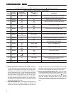
Use the terminal output information below to help you wire the
thermostat properly for your heat pump system. After wiring,
see CONFIGURATION section for proper thermostat configu-
ration.
SYSTEMSYSTEM
SYSTEMSYSTEM
SYSTEM
LL
LL
L
C*C*
C*C*
C*
RR
RR
R
W2W2
W2W2
W2
E/W1E/W1
E/W1E/W1
E/W1
Y2Y2
Y2Y2
Y2
Y1Y1
Y1Y1
Y1
GG
GG
G
OO
OO
O
BB
BB
B
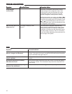
Heat Fault 24 Volt 24 Volt Heat Mode Emergency No Heat and Blower/Fan Energized Energized Energized
Pump 1 Indicator (Common) (Hot) 2nd stage, Mode Output Cool mode on call for Heat in Cool in Heat
or System Emergency 1st stage 1st stage and Cool Mode OFF
Heat Malfunction Mode 2nd 2nd (compressor) Set GAS/ELEC switch Emergency
Pump 2 Switch stage stage for Emergency mode mode
Heat Mode compressor
3rd stage,
Emergency
Mode 2nd
stage
THERMOSTAT TERMINALS (HEAT PUMP)THERMOSTAT TERMINALS (HEAT PUMP)
THERMOSTAT TERMINALS (HEAT PUMP)THERMOSTAT TERMINALS (HEAT PUMP)
THERMOSTAT TERMINALS (HEAT PUMP)
L
R
E/W1
SYSTEM
MONITOR
SWITCH
G W2
2nd Stage
Compressor
CY1
Y2
Compressor
Contactor
Aux
Heat
Relay
Fan
Relay
Emergency
Heat
Relay
TWO COMMONS MUST
BE JUMPERED TOGETHER!
24 VAC 120 VAC
HOT
NEUTRAL
THERMOSTAT
SYSTEM
HOT
NEUTRAL
120 VAC
Limit or
Safety
Switches
Limit or
Safety
Switches
Limit or
Safety
Switches
24 VAC
Limit or
Safety
Switches
COMMON
COMMON
Auxiliary
Heating
Transformer
(Class II
Current Limited)
Heat Pump Transformer
(Class II Current Limited)
24 VAC
ACCESSORY
RELAY N.O.
CONTACT
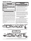
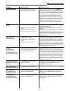
Polarity must be observed. If the HOT side of the second transformer
is jumpered to the COMMON side of the first transformer a short will
be made. Damage to equipment will occur when power is restored.
NOTE
The accessory relay scheme
is required when safety
circuits exist in both systems.
NOTE
Reversing
Valve
Energized in
Heat, Off,
Emergency
Mode
B
Reversing
Valve
Energized in
Cool Mode
O
*
Figure 4. Typical wiring diagram for two transformer heat pump systems with safety circuits in BOTH systems
*The 24 volt neutral connection to terminal C on the thermostat is not required if you replace the batteries once a year with fresh “AA” alkaline batteries.
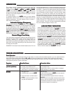
C R
Y2
Compressor
Contactor
Stage 1
Heat
Relay
Stage 1
Heat
Relay
Stage 2
24 VAC 120 VAC
Hot
Neutral
THERMOSTAT
SYSTEM
Y1
E/W1
W2
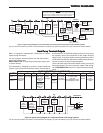
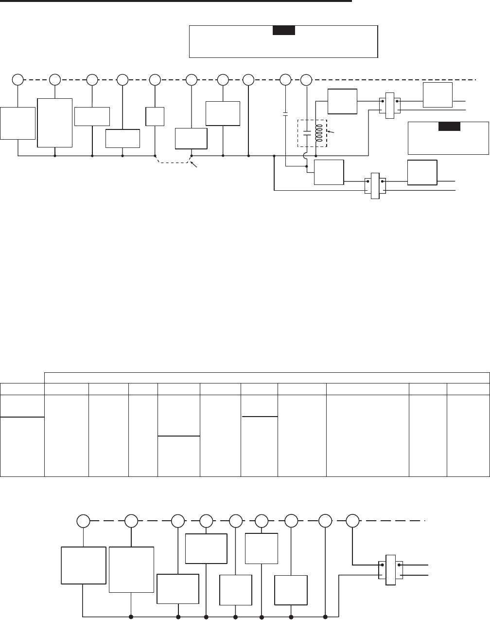
Figure 5. Typical wiring diagram for single transformer multi-stage systems
Fan
Relay
G
TRANSFORMER
(Class II, Current Limited)
Compressor
Contactor
Stage 2
Reversing
Valve
Energized in
Heat Mode
Off Emergency
B
Reversing
Valve
Energized in
Cool Mode
O
*
*The 24 volt neutral connection to terminal C on the thermostat is not required if you replace the batteries once a year with fresh “AA” alkaline batteries.
*The 24 volt neutral connection to terminal C on the thermostat is not required if you replace the batteries once a year with fresh “AA” alkaline batteries.