


7
ETL Model No.: CF921
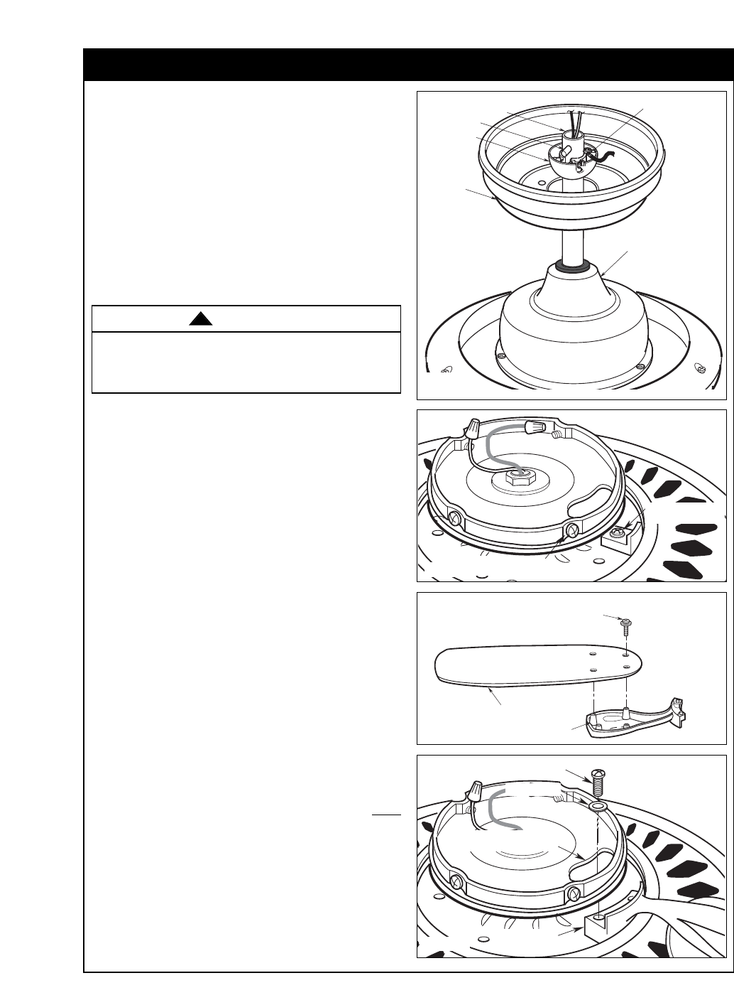
How to Put Your Ceiling Fan Together (continued)
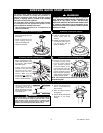
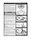
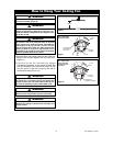
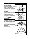
3. Make sure the grommet is properly installed in the
coupling cover, then slide the coupling cover on the
downrod until it rests on the motor housing. Place
the ceiling cover over the downrod. Be sure that
the ceiling cover and the coupling cover are both
oriented correctly (Figure 3).
4. Reinstall the hanger ball (Figure 3) on the downrod
as follows. Route the two 80” motor leads through
the hanger ball. Position the pin through the two
holes in the downrod and align the hanger ball so
the pin is captured in the groove in the top of the
hanger ball. Pull the hanger ball up tight against the
pin and securely tighten the setscrew in the hanger
ball. A loose setscrew could create fan wobble.
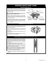
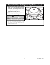
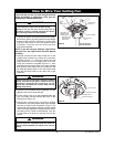
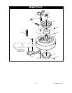
SWITCH HOUSING
MOUNTING PLATE SCREW (4)
SHIPPING SPACERS
AND SCREWS
Figure 4
CEILING
COVER
SETSCREW
PIN
HANGER
BALL
DOWNROD
COUPLING COVER
Figure 3
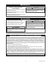
It is critical that the pin in the hanger ball is properly
installed and the setscrew securely tightened.
Failure to verify that the pin and setscrew are
properly installed could result in the fan falling.
WARNING
!
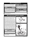
5. The fan comes with black and white leads that are
80” long. Before installing fan, measure up
approximately 6 to 9-inches above top of hanger
ball/downrod assembly. Cut off excess leads and
strip back insulation 1/2-inch from end of leads.
6. Carefully turn the partially assembled ceiling fan
over and set it on the shipping styrofoam for blade
installation.
7. Remove the shipping spacers and the spacer
attachment screws from the motor before
installation of blade assemblies. Discard the
spacers and spacer screws (Figure 4).
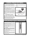
8. Mount blade flanges to fan blades (sold separately)
using four #10-24 x 12mm washer head blade
screws (Figure 5).
NOTE: Some accessory blades available are
supplied with shorter screws. These shorter
screws MUST be used to assemble the blades to
flanges.
NOTE: Take care not to scratch fan housing when
installing blades.
NOTE: Remove and discard the four shipping
spacers and screws from the motor hub.
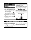
9. Loosely attach one blade assembly to the motor
hub using the two 1/4-20 x 14 captive screws with
lockwashers. Make sure the screws are NOT
tightened. (Figure 6.) Repeat this procedure for
other four blade assemblies.
10. The blade flanges have an interlocking feature
that must be fully engaged before tightening the
screw. Make sure all the flanges are properly
engaged and then tighten the flange screws.
If one of the flanges does not seat properly on the
motor hub, loosen the adjacent flange screws,
re-engage and reseat the flanges, then tighten
the screws again.
FAN BLADE
BLADE FLANGE
#10-24 x 12mm WASHER
HEAD BLADE SCREW (4)
Figure 5
CAPTIVE SCREW
BLADE FLANGE
ASSEMBLY
SWITCH HOUSING
MOUNTING PLATE HOLE
LOCKWASHER
Figure 6