


5
ETL Model No.: CF921
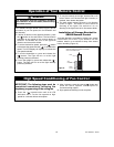
Unpacking Instructions
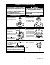
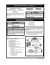
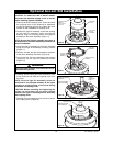
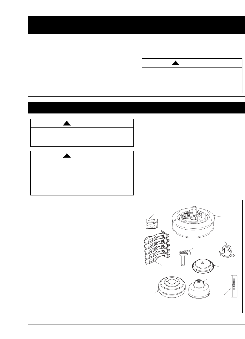
1. Check to see that you have received the following
parts:
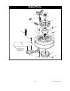
NOTE: If you are uncertain of part description,
refer to exploded view illustration.
a. Fan motor assembly
b. One switch housing assembly
c. One ceiling cover
d. Five blade flanges
e. One hanger ball/downrod assembly
f. One hanger bracket
g. One coupling cover
h. One remote control
i. One loose parts bag containing:
1. Twenty-one #10-24 x 12mm washer head
blade screws
2. One 1/4-20 x 14 captive screw with
lockwasher
3. One #8-32 x 8mm flat head screw
4. One #8-32 x 8mm pan head screw
5. Three wire connectors
6. Two threaded studs
7. Two knurled knobs
This Manual Is Designed to Make it as Easy as Possible for You to Assemble,
Install, Operate and Maintain Your Ceiling Fan
Tools Needed for Assembly
One Phillips head screwdriver One stepladder
One 1/4” blade screwdriver One wire stripper
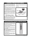
MATERIALS
Wiring outlet box and box connectors must be of
type required by the local code. The minimum wire
would be a 3-conductor (2-wire with ground) of the
following size:
Installed Wire Length Wire Size A.W.G.
Up to 50 ft. 14
50-100 ft. 12
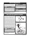
Before assembly your ceiling fan, refer to section
on proper method of wiring your fan (page 10).
If you feel you do not have enough wiring
knowledge or experience, have your fan installed
by a licensed electrician.
Do not install or use fan if any part is damaged or
missing. Call Toll-Free:
1-800-654-3545
This product is designed to use only those parts
supplied with this product and/or any accessories
designated specifically for use with this product by
Emerson Electric Co. Substitution of parts or
accessories not designated for use with this product
by Emerson Electric Co. could result in personal
injury or property damage.
a. FAN MOTOR
ASSEMBLY
d. BLADE
FLANGES
g. COUPLING
COVER
e. HANGER BALL/
DOWNROD
ASSEMBLY
f. HANGER
BRACKET
i. LOOSE
PARTS BAG
c. CEILING
COVER
b. SWITCH
HOUSING
ASSEMBLY
h. REMOTE
CONTROL
WARNING
!
WARNING
!
WARNING
!
8. Two lockwashers
9. One clevis pin
10. One hairpin clip
11. One balancing kit
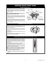
NOTE: Place the parts from the loose parts bags
in a small container to keep them from being lost.
If any parts are missing, contact your local
retailer or catalog outlet for replacement before
proceeding.
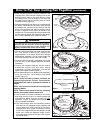
2. Remove the fan assembly from the protective
plastic bag. Place the fan assembly into the upper
foam pad with the bottom of the motor facing up.
The upper foam pad serves as a holder for the fan
during the first stages of assembly.