


15
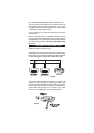
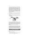
A maximum of 250 metres (820ft) of signal cable can be used,
(maximum resistance between detectors 50 ohm). The units
are interconnected by wiring all the terminals marked 1
together, and all the terminals marked 2 together (as in fig 8)
before screwing the mounting plate to ceiling. Draughts,
through the ceiling, from wiring openings, conduit, or mount-
ing boxes/holes, may blow smoke away from the sensing
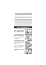
chamber, making it insensitive. It is essential that all such
openings including the wiring hole (see figure 9) be closed by
silicone sealant or similar.
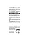
1. Remove the Smoke Alarm from the mounting plate as
shown in fig 1a
2. Lift the wiring cover on the mounting plate as shown in fig 9.
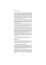
3. Connect the two core cable to the terminal block as shown
in fig 10.
4. Replace the wiring cover and attach the smoke alarm to the
mounting plate.
After wiring together the Interconnect Smoke Alarms, test the
first unit by pressing the button. All the detectors should
alarm and the test button on the first unit will flash about once
a second. Please note it can take up to 5 seconds for some
of the interconnected units to sound. Check all the other units
similarly.
Check the Radio Interconnect as described above.
These Smoke Alarms should be interconnected only within
the confines of a single family living unit. If they are connect-
ed between different units there may be excessive nuisance
alarms. Everybody may not be aware that they are being test-
ed or that it is a nuisance alarm caused by cooking etc.
8. IMPORTANT SAFEGUARDS
When using household protective devices, basic safety pre-
cautions should always be followed, including those listed
below
¥ Please read all instructions.
¥ Rehearse emergency escape plans so everyone at home
knows what to do in case the alarm sounds.
Figure 10