


power the system in standby for a week followed by at least 4
minutes alarm. When the mains fails, the green light is extin
-
guished and thered light flashes rapidly onthe control panel to
indicate it is on battery power. If the battery is starting to be
fully depleted the red light will go off to indicate the control
panel is totally unpowered. The battery will last 5 years in nor
-
mal use provided it is not exposed to extremes of temperature
for prolonged periods, or fully discharged/charged a large
number of times.
We recommend that the functioning of the rechargeable
battery is checked at least yearly as follows:
(i) Ensure the control panel has been mains powered for at
least the previous 20 hours for the battery to charge.
(ii) Turn off the mains power to the control panel by unplug
-
ging it or switching off the circuit at the distribution board.
Check that the green light goes off and the red light starts to
flash.
(iii) Press the control panel test button for 20 seconds and
check the strobe flashes brightly and that the pad vibrates
strongly. Check that the red light continues to flash while the
test button is pressed. (Cover the strobe light with card to stop
this dazzling you while looking for the red light). This red light
flashing indicates that the battery is satisfactory. If the red light
goes off, or if the strobe is weak, or if the vibration is weak, the
battery will need to be replaced. Contact the nearest address
in this leaflet for advice about getting a replacement.
3. Troubleshooting
If the units fail any of the tests after installation outlined
above, the system has probably been incorrectly wired and/or
all units are not connected. Check all wiring carefully. If the
green power lights on the smoke alarm and/or the control
panel are not on, check the wiring to the mains and that the
mains is not off (e.g. due to a tripped circuit breaker or fuse).
Check the power switch on the control panel is on.
The control panel monitors the wiring to the vibration pad
and the smoke alarm pattress for faults.
(i) If the vibration pad is removed or if its wiring is open cir
-
cuit, the control panel will flash the strobe.
(ii) If the wiring to the smoke alarm pattress is disconnected,
open circuited or short circuited, the control panel will turn on
the vibration pad and the strobe light.
There are no user serviceable parts in this unit. If it is though
to be defective, it must be returned to the manufacturer for re
-
pair or replacement (see “Product Guarantee” section).
4. Accessories and other Features
Control Panel “Aux. Output”
The auxiliary output turns on when the control panel is in
alarm and can supply up to 200 mA at 12 Volts (range 10 to 14
Volts). (Note: the positive terminal is the pin next to the
“Clock Input” socket). An Auxiliary Strobe
EI 178 is available
and is supplied with10 m of cable and a suitableplug. It can be
located, for example, where it is readily seen during the day
(e.g. downstairs hallway). An extra Vibration Pad
EI 174 is
available with 2 m of cable and a plug for connecting it to the
auxiliary socket.
Control Panel “Clock Input” socket
A suitable alarm clock (with a 5 to 24 Volts AC or DC output -
electrically isolated from the mains supply) can be connected
to this input socket with a 3.5 mm mono jack plug. When the
alarm clock triggers, the vibration pad turns on to wake the
person, but the internal strobe or auxiliary output do not turn
on.This lets the user know it is a wake-up call and not a fire.
Therefore the user needs only one vibration pad under their
pillow or mattress.
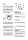
Triggering Control Panel into Alarm Externally
A manual fire alarm switch (e.g. a glass break type) can be
used to get the control panel to turn on the vibration pad and
strobe light. This is done by connecting the red and yellow
wires, from the control panel, together, with the switch (or
volt-free relay isolated contacts). The wires from the switch
can be connected into the circuit at the pattress terminals.
Note: This does not cause the smoke alarm to sound.
Adding an EI 158 Smoke Alarm Pattress with relay
to the system
The EI 158CS/158P Pattress is used where volt-free relay
contacts are required tosignal to other equipment whenone of
the smoke alarms sense fire. For example the relay can be
used to signal to a warden call system, or to turn on lights.
If there are more than two smoke alarms in the system the
first smoke alarm can be mounted on the opto-isolator pat
-
tress
EI 172 asdescribed above. The secondsmoke alarm, in
-
terconnected to the first, can be mounted on the relay pattress
EI 158CS / EI 158CSR or EI 158P / EI 158PR. When any
smoke alarm senses fire the
EI 172 pattress will signal the
control panel into alarm and the
EI 158 pattress will switch its
relay contacts. Note: If both an
EI 172 and an EI 158 are being
used only 6 smoke alarms may be interconnected together on
the system.
Power Requirements
The typical currents at 230 VAC are
·
Standby 10 mA
· Alarm 50 mA
5. Product Guarantee
Ei Electronics guarantees this system for one year from the
date of purchase against any defects that are due to faulty ma-
terials or workmanship. This guarantee only applies to normal
conditions of use and service, and does not include damage
resulting from accident, neglect, misuse, unauthorised dis
-
mantling, or contamination howsoever caused. This guaran
-
tee excludes incidental and consequential damage. If this
system should become defective within the guarantee period,
it must be returnedto the nearest address in thisleaflet. It must
be carefully packaged with the power switch on the control
panel in the off position, and with the problem clearly stated
along with proof of the date of purchase. We shall at our dis
-
cretion repair or replace the unit. Do not interfere with the sys
-
tem or attempt to tamper with it. This will invalidate the
guarantee, but more importantly may expose the user to
shock or fire hazards.
This guarantee is in addition to your statutory rights as a con
-
sumer.
Manufactured by Ei Electronics.
Shannon, Co. Clare Ireland.
© 2001
P/N B12206