


Panel, but the mains transformer remains connected to the
supply mains.
Vibration Pad
Plug the vibration pad into its locking socket on the control
panel. Place the vibration pad under the pillow or mattress. It
is important that the person in the bed can feel the vibration -
check it is sufficient to wake a person by lying on the bed and
pressing the test button on the control panel - see also “Test
-
ing your system”. Some mattresses may not transmit suffi
-
cient vibration, and in these cases it should be fitted under the
pillow. Note: During testing, or in an actual alarm situation,
the pad pulses on and off for greater effect on sleepers.
Mains Smoke Alarm Interface Pattress EI 172
The pattress isused to mount thesmoke alarm in itslocation,
to connect it to the mains and interconnect wires, and to con
-
nect it to the wires from the
EI 173 control panel. (The connec
-
tions from the non-isolated mains powered smoke alarms, to
the low voltage control panel wires are through an opto-
isolator in the
EI 172 for electrical safety).
1. Choose the mounting position following the siting instruc-
tions in the Smoke Alarm leaflet. Remove the power from the
circuit you plan to use. The HMSO Building Regulations state
that self-contained Smoke Alarms should be permanently
wired to a separately fused circuit at the distribution board.
2. Where the incoming mains and interconnect wires are on
the surface of the ceiling or wall the appropriately sized duct
-
ing/conduit must be chosen to mate with the unit.
3. The low voltage wiring from the control panel must not be
run in the same conduit as the mains/interconnect wires.
4. Using a sharp knife remove material from the appropriate
knockouts making sure that there is no gap, either where
mated with the ducting/conduit or with the low voltage wires.
There are five knockouts, four on the sides and one on the
rear.
5. Screw the pattress to the surface using the two screws
and plastic plugs supplied.
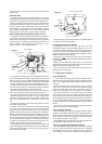
6. Figure 1 shows the connections. Connect the incoming
live, neutral, and interconnect (from other smoke alarms if
present) to the pre-wired connector block. If an earth wire is
present connect it to the fourth terminal as shown. The Smoke
Alarm connector plug isalready wired to the pattress. Connect
the red wire (remove the small piece of insulating tape first)
from the control panel to the terminal marked “R” and the yel
-
low wire to the terminal marked “Y”. The black and blue wires
from the control panel are not used. They should both be con
-
nected to the spare terminal for extra strain relief.
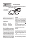
7. Bring the connector plug out through the rectangular hole
in the mounting plate, line up the latch with its recess and then
screw the mounting plate on to the box as shown in figure 2
with the screws provided.
8. Push theplug on to thepins in the rearof the Smoke Alarm
and slide on to the mounting plate.
Interconnecting Smoke Alarms
A maximum of 12 EI 150/ 151/ 153/ 154/ 155/ 156
Smoke/Heat Alarms may be interconnected to one
EI 172
unit. When one alarm senses fire all interconnected units will
sound and the control panel will turn on the strobe light and vi
-
bration pad (See Smoke Alarm instruction leaflet for further
details on
interconnection wiring).
Warning
: Do not connect to any other type of Smoke Alarm.
Doing this may damage the alarms and could result in a shock
or fire damage.
Note 1: An alarm with battery back-up (i.e.
EI 151/154/156)
will continue to operate during mains failure and will be able to
signal the control panel if they sense fire.
The control panel also has battery back-up, so that it too will
operate during mains failure.
2. Testing your System
After Installation
1. Turn on the AC mains power to the smoke alarm circuit.
Check the continuous greenlight is visible on thesmoke alarm
cover. The red light behind the test button will flash every 40
seconds.
2. Plug in the control panel mains adaptor (or turn on the AC
mains if it is connected to a junction box). Slide the power
switch on the side of the unit to the “on” position. Check the
continuous green light on the control panel cover is visible.
3. Press the test button on the smoke alarm. The smoke
alarm should sound and the red light behind the button will
flash every second. After about 4 seconds the control panel
will start flashing the strobe light and the vibration pad will turn
on. Two people may be needed for this test. Interconnected
smoke alarms (where present) should also be tested in similar
fashion.
4. Press the control panel test button. Check the vibration
pad is on and that the strobe is flashing.
Daily & Weekly Testing
We recommend that you test your system weekly by press
-
ing all the smoke alarm test buttons and checking that the vi
-
bration pad and strobe light are operating. Also check at the
same time that the green power lights are visible on both the
smoke alarm(s) and the control panel.
Check daily that the vibration pad is in its correct position by
pressing the test button on the control panel.
Periodic Testing of Rechargeable Battery
The rechargeable battery takes about 20 hours to charge
from the control panel when it is first powered up. The panel
then maintains it in the fully charged state by continuous
trickle charge. In the event of a mains failure the battery will
2
Figure 1
Figure 2
PLATE FIXING SCREWS
CONDUIT
SMOKE ALARM
CONNECTOR
LATCH RECESS
TO CONTROL PANEL Ei 173
EARTH (IF PRESENT)
LICNE
L
IC
N
R (RED)
Y (YELLOW)
SPARE TERMINAL
LIVE
INTERCONNECT
TO OTHER SMOKE
ALARMS (IF PRESENT
NEUTRAL
CONDUIT
PLUG IN TO SMOKE ALARM
SLEEVE
TO CONTROL PANEL Ei 173
MOUNTING SCREW
HOLES (4)