


2. Testing your System
After Installation
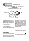
1. Turn on the AC mains power to the smoke alarm circuit.
Checkthecontinuousgreenlightisvisibleonthesmokealarm
cover. The red light on the unit will flash every 40 seconds.
2. Pluginthe controlpanel mainsadaptor(or turnon theAC
mains if it is connected to a junction box). Slide the power
switch on the side of the unit to the “on” position. Check the
continuous green light on the control panel cover is visible.
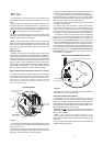
3. Press the test button on the smoke alarm. The smoke
alarm should sound and the red light will flash every second.
After about 4 seconds the control panel will start flashing the
strobe lightandthe vibrationpad willturnon. Twopeople may
be needed for this test. Interconnected smoke alarms (where
present) should also be tested in similar fashion.
4. Press the control panel test button. Check the vibration
pad is on and that the strobe is flashing.
Daily & Weekly Testing
We recommend that you test your system weekly by press
-
ing all the smoke/heat alarm test buttons and checking that
the vibrationpad and strobelight areoperating. Also checkat
the same time that the green power lights are visible on both
the smoke alarm(s) and the control panel.
Check dailythat thevibration padis inits correctposition by
pressing the test button on the control panel.
Periodic Testing of Rechargeable Battery
The rechargeable battery takes about 20 hours to charge
from the control panel when it is first powered up. The panel
then maintains it in the fully charged state by continuous
trickle charge. In the event of a mains failure the battery will
power the system instandby for a week followedby at least4
minutes alarm. When the mains fails, the green light is extin-
guishedandtheredlightflashesrapidlyonthecontrolpanelto
indicate it is on battery power. If the battery is starting to be
fully depleted the red light will go off to indicate the control
panel istotally unpowered.The batterywill last 5years innor-
mal useprovidedit isnot exposedtoextremes oftemperature
for prolonged periods, or fully discharged/charged a large
number of times.
We recommend that the functioning of the rechargeable
battery is checked at least yearly as follows:
(i) Ensurethe controlpanelhas beenmains poweredfor at
least the previous 20 hours for the battery to charge.
(ii) Turn offthe mains power tothe control panel byunplug
-
ging it or switching off the circuit at the distribution board.
Check that the green light goes off and the red light starts to
flash.
(iii) Press the control panel test button for 20 seconds and
check the strobe flashes brightly and that the pad vibrates
strongly. Check that the red light continues to flash while the
test button is pressed. (Cover the strobe light with a card to
stop thisdazzling youwhile looking forthe redlight). This red
lightflashingindicates thatthebatteryissatisfactory.If thered
lightgoesoff,orifthe strobeisweak,orifthevibrationisweak,
the battery will need to be replaced. Contact the nearest ad
-
dress in this leaflet for advice about getting a replacement.
Replace Ei173 control panel after 5 years operation. (See
date on side of panel).
3. Troubleshooting
If the units fail any of the above tests after installation, the
system has probably been incorrectly wired and/or all units
are not connected. Check all wiring carefully. If the green
power lights on the smoke alarm and/or the control panel are
not on, checkthe wiring tothe mains andthat the mainsis not
off (e.g. due to a tripped circuit breaker or fuse). Check the
power switch on the control panel is on.
The control panel monitors the wiring to the vibration pad
and the smoke alarm pattress for faults.
(i) If the vibration pad is removed or if its wiring is open cir
-
cuit, the control panel will flash the strobe.
(ii)If thewiringto thesmokealarm pattressisdisconnected,
open circuited or short circuited, the control panel will turn on
the vibration pad and the strobe light.
Thereare nouserserviceable partsinthisunit. Ifitis thought
to be defective,it must bereturned to the manufacturerfor re
-
pair or replacement (see “Product Guarantee” section).
4. Accessories and other Features
Control Panel “Aux. Output”
The auxiliaryoutput turns onwhen thecontrol panel isin alarm
and can supply up to 200 mA at 12 Volts (range 10 to 14 Volts).
(Note:the positiveterminal isthe pinnext tothe “ClockInput”socket).An
Auxiliary Strobe
Ei 178 isavailable and issupplied with10 m of
cable anda suitable plug.It can belocated, for example,where it
is readily seen duringthe day (e.g. downstairs hallway).An extra
Vibration Pad
Ei 174is availablewith 2m of cableand aplug for
connecting it to the auxiliary socket.
Control Panel “Clock Input” socket
A suitable alarm clock (with a 5 to 24 Volts AC or DC output -
electrically isolated from the mains supply) can be connected to
this input socket with a 3.5mm mono jack plug. When the alarm
clock triggers, thevibration pad turns on to wakethe person, but
the internal strobe or auxiliary output do not turn on.This lets the
user know it is a wake-up call and not a fire. Therefore the user
needs only one vibration pad under their pillow or mattress.
Triggering Control Panel into Alarm Externally
Amanualfirealarm switch(e.g.aglassbreaktype)canbeused
to get the control panel to turn on the vibration pad and strobe
light.Thisisdonebyconnectingtheredandyellowwires,fromthe
control panel, together,with the switch (orvolt-free relay isolated
contacts).Thewiresfromtheswitchcanbeconnectedintothecir
-
cuit at the pattress terminals.
Note: This does not cause the smoke alarm to sound.
Adding an Ei 128R Pattress with relay to the system
The Ei128R Pattress isused wherevolt-free relay contactsare
required to signal to other equipment when one of the smoke
alarmssensefire.Forexampletherelaycanbeusedtosignalto a
warden call system, or to turn on lights.
This requires the system to have at least two smoke/heat
alarms. The first smoke/heat alarm should be mounted on the
pattressEi172/160asdescribedabove.Thesecondsmoke/heat
alarm, interconnectedto thefirst, shouldbe mountedon therelay
pattress Ei 128R. When any smoke alarm senses fire the Ei
172/160pattress willsignalthecontrol panelintoalarmandthe Ei
128R pattress will switch its relay contacts.
(Note: TheEi128R willnot operatewithouta 230VACmains
supply).
Power Requirements
The typical currents at 230 VAC are
·
Standby 10 mA
·
Alarm 50 mA
6
5