


brown: live
blue: neutral
The wire which is coloured blue must be connected to the
terminal/wire which is marked with the letter N or coloured
black.
The wire which is coloured brown must be connected to the
terminal/wirewhichismarkedwiththeletterLorcolouredred.
The apparatusisnot tobeearthed, sono connectionisto be
made to terminals or wires markedwith the letter E,the sym
-
bol or coloured green or green and yellow.
Bring the low voltage wiring from the control panel to where
the smoke alarm is to be located. Route all wires neatly and
securely along the walls and ceilings.
Note: Turning off the power switch on the Control Panel
does notswitch off theapparatus from thesupply mains. The
switch removes the AC and battery power from the Control
Panel, but the mains transformer remains connected to the
supply mains.
Vibration Pad
Plug the vibration pad into its locking socket on the control
panel. Place the vibration pad under the pillow or mattress. It
is important that the person in the bed can feel the vibration -
check it is sufficient to wake aperson by lying on the bed and
pressing the testbutton on the controlpanel - seealso “Test
-
ing your system”. Some mattresses may not transmit suffi
-
cient vibration,and inthese casesit shouldbe fittedunderthe
pillow. Note: During testing, or in an actual alarm situation,
the pad pulses on and off for greater effect on sleepers.
Mains Smoke Alarm Interface Pattress Ei 172/160
Thepattressisusedtomountthesmokealarminitslocation,
to connect it to the mains and interconnect wires, and to con-
nect it to the wires from the Ei 173 control panel.
(The connec-
tions from thenon-isolated mains powered smokealarms, to the low
voltage control panel wires are through an opto-isolator in the Ei
172/160 for electrical safety).
1. Choosethemounting positionfollowing thesiting instruc
-
tions in the Smoke Alarm leaflet. Remove the power from the
circuit you plan to use.
2. Wherethe incomingmains andinterconnect wires areon
the surface of the ceiling or wall the appropriately sized duct
-
ing/conduit must be chosen to mate with the unit.
3. Thelow voltagewiring from thecontrol panelmust notbe
run in the same conduit as the mains/interconnect wires.
4. Usinga sharpknife removematerial fromtheappropriate
knockouts making sure that there is no gap, either where
mated with the ducting/conduit or with the low voltage wires.
There are three knockouts and one on the rear.
5. Screw the pattress to the surface using the two screws
and plastic plugs supplied.
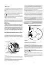
6. Figure 1 shows the connections. Connect the incoming
live, neutral, and interconnect (from other smoke alarms if
present) to the pre-wired connector block. The Pattress does
not require an Earth. The three wires for connecting to the
smokealarmmountingplatearealreadywiredtothepattress.
Connect the red wire (remove the small piece of insulating
tape first) from the control panel to the terminal marked “R”
and the yellowwire to theterminal marked “Y”. Theblack and
blue wires from the control panel are not used. They should
bothbeconnectedtothespareterminalforextrastrainrelief.
7. Bringthe mountingplate wires outthrough thehole inthe
mounting plate as shown in figure 2. Connect the three wires
to the mounting plate terminals following the wiring colours
specifiedinfigure2.Note:Thewhiteinterconnectwiremust
be connected to the smoke alarm (even if there is only one
smoke alarm on the system).
8. Replacethe wiringcover onthe mounting plate.Slide the
Smoke Alarm on to the mountig plate.
Interconnecting Smoke Alarms
A maximum of 12 Ei 140,141,144,145,146,161,164,166
Smoke/HeatAlarmsmay beinterconnectedtooneEi172/160
unit. When one alarm senses fire all interconnected units will
sound andthecontrol panelwill turnon thestrobe lightandvi
-
bration pad (SeeSmoke/Heat Alarm instructionleaflet for fur
-
ther details on
interconnection wiring).
Warning
: Do not connect to any other type of Smoke/Heat
Alarm.Doingthismaydamagethealarmsandcouldresultina
shock or fire damage.
Note 1: An alarm with battery back-up (i.e. Ei
141,144,146,161,164,166) will continue to operate during
mainsfailure andwillbe ableto signal thecontrolpanel ifthey
sense fire.
The control panelalso has batteryback-up, so thatit too will
operate during mains failure.
3
L
IC
N
R
Y
N
IC
L
TO EASI-FIT SMOKE ALARM
MOUNTING PLATE
Figure 1
PATTRE
SS
WIRING
TO OTHER SMOKE/HEAT
ALARMS (IF PRESENT)
NEUTRAL
INTERCONNECT
LIVE
REMOTE
CONDUIT
TO CONTROL
PANELEi173
N
IC
L
- BLUE
- WHITE
- BROWN
-RED
- YELLOW
-
SPARE TERMINAL
WIRING FROM PATTRESS Ei172/160
PLATE
FIXING
SCREWS
SMOKE ALARM MOUNTING PLATE
Figure 2
INTERCONNECT (WHITE)
LIVE (BROWN)
NEUTRAL (BLUE)
LICN
4