4
size, are electrically charged (positively) as they pass
through a high voltage ionizer. These charged particles
are then attracted and adhere to a series of parallel
collecting plates, which form the negative elements of
an electrostatic field.
The ionizer consists of charged stainless steel spiked
blades spaced between grounded electrodes. The
collecting section consists of parallel plates arranged so
that each alternate plate is charged while the
intermediate plates are electrically grounded.
Periodically, depending on the type and concentration of
contamination in the air, contaminate is washed from
the plates by manually removing the cells and washing
with a pressure washer.
Two major functional components comprise the air
cleaner:
(1) Ionizing-collecting cells to ionize and collect
airborne particulate matter.
(2) Power supply(s) to supply high voltage direct
current to the ionizing-collecting cells.
Normally, systems are designed for collection
efficiencies in the range of 90 percent or more.
Collecting a contaminate at these efficiencies,
especially when there are high concentrations can result
in large accumulations in a relatively short period.
Therefore, maintenance must encompass two areas;
the operation of the equipment for efficient collection
and the systematic removal of the collected
contaminate.
2. General Description
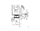
The ionizing-collecting cells (contaminate collecting
elements) are housed in the cabinet on slide rails. They
can be removed from the cabinet as required, through
the end access door, by sliding them out like drawers.
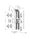
On multi-cell units, all of the electrical connections
between cells in a given tier are automatically made
through spring plunger connectors. On the access end,
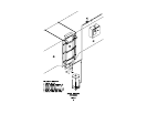
the high voltage cables from the power supplies are
connected to the junction box on top of the cabinet. The
high voltage cables from the junction box to the
individual tiers are factory wired. When installing cells
into the cabinet, observe the directional arrows on the
cell end plates. The side of the cell containing the
spiked ionizer blades always must be located on the air
entering side. The spring plunger connectors, located
on one end of each cell, will always face toward the
back of the Model 75 Cabinet.
Both the air entering and air leaving side of the cabinet
contain either metal mesh filters or perforated plate,
whichever was specified. These items act as trash
screens, and provide resistance for even air distribution.
The Power Supply(s) convert the 115 volt, 60HZ, single
phase AC supply to the high voltage DC needed to
power the ionizing-collecting cells. Potential of 13 KVDC
are required for the ionizer sections and 6.5 KVDC for
the collector sections of the cells.
3. Initial Start-up
A. Inspect the inside of the adjoining ductwork and
Trion cabinet to be sure it is clean and free of any
debris or construction materials. Especially note the
opening in the drain basin for any restrictions. The
ducting, where secured to the cabinet collars,
should be sealed water tight either with gasketing or
caulking.
B. Inspect the ionizing-collecting cells to see that all of
the ionizing blades are intact, that no large pieces of
foreign material are lodged between the plates, and
that the cells are properly installed in the cabinet
with the spiked ionizing blades located on the air
entering side.
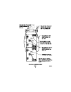
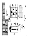
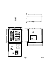
C. Check the high voltage leads to see that they are
connected to the proper terminal both at the
ionizing-collecting cells, the junction box and inside
the controller. (Refer to Figures 2 and 4).
D. Be sure that the drain lines from the Trion cabinet
drain basin are completely connected and properly
terminated. A trap or seal of some type should be
incorporated in the line to prevent air bypass.
E. Be sure that electrical power is available, that the
wiring is completed, and that the system blower is
ready to energize.
F. Be sure that all access door interlocks are closed.
G. Close the system electrical supply switches, making
power available to the Trion controller and the
system fan.
H. Turn the controller selector switch to the “ON”
position. The blower should run (if installed) and the
power supply(s) should be energized. Electrical
arcing within the ionizing-collecting cells may occur.
It is a normal occurrence caused by accumulation of
dusts from construction or other sources in the
cell(s) and should subside quickly. If the arcing is
continuous and does not subside, recheck the
routing of the high voltage leads between the power
supply(s) and the cell(s). Refer to the field wiring
diagram. The ionizer lead must be connected to the
ionizer and the collector lead to the collector.
Kitchen Exhaust Applications
I. For safe and proper operation adhere to the following
instructions and procedures:
1. Exhaust systems shall be operated during all
periods of cooking in restaurant applications.


