


Installing Projector
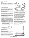
The video projector should be suspended from the trav el ing pan ac cord ing
to projector manufacturer’s instructions or using optional SMS Low Profi le
Mount, and using rec om mend ed standard ceiling mounting hardware (“Z”
brackets are attached to bottom side of traveling pan for easier installation).
If SMS Low Profi le is used, remove aluminum adaptor bracket from LCD Lift.
Use SMS Low Profi le to mark hole locations on aluminum adaptor bracket,
drill holes, attach SMS Low Profi le Mount, then slide adaptor bracket, with
SMS Low Profi le Mount attached, back into Z brackets.
NOTE: Draper Inc. provides an optional aluminum adaptor bracket or an
optional mount for your projector. Please consult the instruction sheet
packed with the adaptor bracket for installation information.
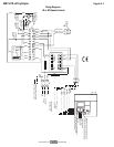
The LCD Lift has a grounded 220-240V AC, 50Hz outlet for pro jec tor power
supply. Power is supplied to this outlet when unit is in “fully down” po si tion. An
AC current sensor has been factory installed and will not allow the projector
to rise into the LCD Lift until the pro jec tor has been cooled by its ventilation
fan(s). When the fan(s) stop op er at ing, the LCD Lift will raise the projector into
its stored position.
Knockouts are provided for passage of signal and control cables.
Unit and projection system should be operated, checked and ad just ed as
necessary at this time.
Warning: Keep fi ngers and other objects away from automatic doors and
traveling pan when unit is operating. Serious injury or damage could
result.
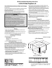
Dimensions of Traveling Pan
A B C
LCD Lift A 46 cm 32 cm 3 mm
LCD Lift B 58 cm 45 cm 5 cm
Page 3 of 4
A
A
B
C
C
67 mm
45 cm
67 mm
35 mm
Z brackets and
adaptor plate for
mounting projector.
35 mm
220V LCD Lift by Draper
SMS Low Profi le with Universal Bracket
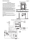
Wiring Diagram—Single Station Control
1 2 3 4 5 6 7 8 9 10
1 2 3 4 5 6 7 8 9 10
Red
Yellow
Black
Red - Up
Black - Common
Yellow - Down
Wall Switch
SPDT Center Off
220 V AC
Supply
Black
White
White
Black
Black
Black Black
Black
Black
Black
BlackBlack
Black
1 2 3 4 5 6 7 8 9 10 11 12 13 14 15 16
Yellow
Red
Red
Red
Red
White
White
White
Capacitor
Motor
Black - Down
Red - Up
White - Neutral
Dashed wiring by electrician
Duplex Outlet
Switched on only in
the fully down position
Black
White
Receptacle
Limit Switch
LS1 NO
Down Travel
Limit Switch
LS2 NC
Up Travel
Limit Switch
LS3 NC
Black
Red
AC Current
Sensor
1 2 3 4 5
Receptacle Lmt
switch (LS4)
NC
5A
5A
5
6
7
Yellow/
Green
1
2
3
NEU
L1
GND
Yellow/
Green
TB1
TB1
TB2
Yellow/
Green
www.draperinc.com
(765) 987-799
9
124 mm