


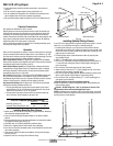

Installing Bomb Bay Door Closure
➀ Attach closure to LCD Lift frame with factory supplied hardware. Bomb bay
doors should be hanging straight down.
➁ Lower unit until traveling pan is approximately 10 cm above its lowest
position.
➂ Install supplied ball chain to connectors attached to the eye bolts threaded
into angles on traveling pan (See Fig. 2).
➃ Install ball chain to connectors attached to bomb bay doors.
➄ Raise unit to highest position. Doors should close com plete ly.
➅ If the doors do not close completely, lower unit and adjust the eye bolts until
doors close completely.
➆ Once “closed” position has been accomplished, lock eye bolts into place
with hex jam nuts.
➇ Adjust the LCD Lift to the height of the fi n ished ceiling.
Figure 3
Page 2 of 4
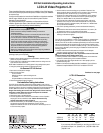
LCD Lift—Required Space Above Ceiling
LCD Lift A LCD Lift B
Bomb Bay Closure (cm) 47 60
Universal (Flat) Ceiling Closure (cm) 49 62
Figure 2
Operation
When unit is fi rst operated, be cautious. If doors or closure panel do not begin
to open mo men tari ly when switch is fl ipped “down”, return switch to “off” and
free doors and/or recheck electrical con nec tions before pro ceed ing. Cycle unit
down and up several times to confi rm satisfactory operation.
220 V Single Sta tion Control (CE Approved)—3-position UP-OFF-DOWN
switch per mits op er a tion to be stopped at any point. Factory set limit switch es
au to mat i cal ly stop lift when fully down or fully up.
220 V Multiple Station Control (Not CE Approved)—Switches are similar
in ap pear ance to Single Station Control. Lift stops when switch is re leased
and may be re start ed in either direction. Factory set limit switches stop lift
au to mat i cal ly when fully up or fully down.
24 V Control (CE Approved)—Three-button UP-STOP-DOWN switches stop
at any point desired, operate in any sequence. Factory set limit switch es
au to mat i cal ly stop lift when fully up or fully down. Wire less con trols—whether
infrared or radio fre quen cy—interface with low voltage control box.
Key Operated Switching (Not CE Approved)—Two kinds of key-operated
switches are op tion al ly available with this unit.
➀ The key-operated power supply switch controls power to the lift and
switches. When it is “off”, the switches will not op er ate lift. Key may be
removed from the switch in “on” or “off” position.
➁ A three-position key switch permits the lift to be op er at ed directly by
key. In this case, the lift’s operator must have a key.
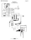
Electrical Connections
Unit operates on 220-240V AC, 50 Hz. current.
Opening electrical control box exposes terminals for fi eld con nec tions. Unit
is shipped with internal wiring complete and control switch(es) boxed. Wire
con nect ing unit to switch(es) and to power supply should be furnished by
in stall er. Con nec tions should be made in accordance with wiring di a gram, and
wiring should com ply with national and local elec tri cal codes. All op er at ing
switches should be “off” before power is con nect ed.
LCD Lift should be operated and checked prior to installing bomb bay doors,
universal (fl at) ceiling closure or projector.
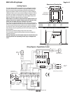
Ball chain for
bomb bay doors
Threaded rod to
ceiling closure panel
Threaded rod for
unit suspension
Universal Closure Bomb Bay Doors
220V LCD Lift by Draper
➄ Access should be provided to electrical control box in case service is
required.
➅ Do not use unit to support adjacent ceiling, light fi xtures, etc.
➆ Do not complete the ceiling below unit until electrical connections have
been completed and unit has been operated successfully.
➇ We recommend safety cables be attached to LCD Lift for added security.
www.draperinc.com
(765) 987-799
9
Installing Optional Ceiling Closure
If your LCD Lift is equipped with an optional ceiling closure system, it can be
used as is, or in conjunction with a piece of existing ceiling tile.
➀ If installing with ceiling tile, you may need to cut tile so that its overall
dimensions are the same as (or slightly less than) the closure panel. Place
tile into trim frame. Lay closure panel on top (back side) of ceiling tile, and
tighten screws to hold in place.
➁ If installing large closure, attach brackets to bottom of projector plate
(see drawing at right).
➂ Attach
5
/
16
" threaded rods to slots in projector plate or brackets.
➃ Run unit “up” until bottom pan stops at highest position. Mark po si tion on
5
/
16
" rods even with ceiling level and cut rods to length (removing from
pan if convenient).
➄ Run unit “down” until bottom pan stops at “show” position.
➅ Attach closure to lower end of
5
/
16
" rods by slipping into four corner slots
and secure with nuts above and below slots.
➆ Run unit “up” again to highest position. Measure distance by which panel
fails to reach required “closed” height for sur round ing ceil ing.
➇ Run unit “down” then re-adjust mounting of
5
/
16
" rods in traveling grid to
raise panel required distance.
Caution: Make sure nuts are completely tightened.
➈ Test unit operation to confi rm that panel will stop in closed position just
before touching ceiling.
Caution: DO NOT hang from, "ride" or pull down on the unit. This
could create a failure and cause damage and/or injury.
NOTE: Immediately upon completion of the surrounding ceiling, unit should
be operated to confi rm that optional ceiling closure panel stops just short of
touching ceiling in closed position.