


Planning
➀ Based on screen location and projector specifi cations, determine proper
position for projector installation.
➁ Confi rm that there is adequate space available above the ceiling: 49 cm for
LCD Lift A; 62 cm for LCD Lift B.
NOTE: Add an additional 2 cm of ceiling space if using ceiling closure panel.
➂ Arrange to provide service access to electrical control box.
As Soon as LCD Lift Arrives:
➀ Open carton and inspect for damage.
➁ Locate the following parts:
A. The unit itself
B. Bomb bay doors or optional ceiling closure
C. Controls
D. Optional SMS Low Profi le Mount with Universal Bracket
➂ Follow Pre-Installation Testing Procedure.
Note: Unit has been thoroughly inspected and tested at factory and found to be
operating properly prior to shipment.
220 Volt Installation/Operating Instructions
LCD Lift Video Projector Lift
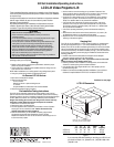
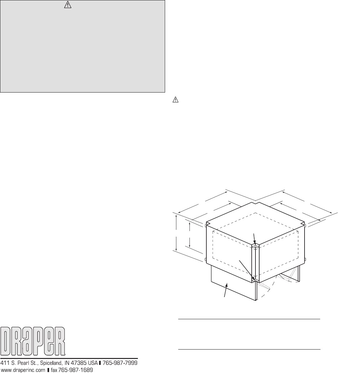
LCD Lift Dimensions
Figure 1
A
C
B
D
A
C
For 12.7 mm threaded rod
(supplied by others)
Bomb bay door assembly standard.
Flat ceiling closure panel available.
14.3 mm dia.
mounting holes
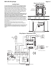
Pre-Installation Testing Instructions
This LCD Lift was extensively tested and in perfect condition when it left our
plant. To make sure that it arrived in the same condition, please use the following
procedure to test the unit prior to installation. Draper does not accept back charges
for labor. Make sure that this unit is operating satisfactorily before installation.
Danger! The traveling pan can exert over 30 kg of force. Do not insert any
body parts or other objects into this unit while power is con nect ed.
➀ Remove the unit from the outer carton.
➁ Remove the cover of the electrical box.
➂ Pre-wire supplied controls and make sure the switch is in the off position
and plug the unit into a 220V AC outlet. Caution: Do not touch any
exposed wires while the unit is plugged in.
➃ Inside the electrical box you will fi nd that a tem po rary plug has been
connected to the terminal board. Extend this plug from the box.
Replace the electrical box cover so that the cover is held loosely (so as not
to crush the wires) in place.
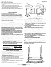
Hanging Unit
The LCD Lift may be installed in a variety of ways. Typically, it is re cessed above
the ceiling and supported by four ½" (12.7 mm) threaded mount ing rods. The
bottom of the LCD Lift should be recessed ap prox i mate ly 4 cm above the fi nished
ceiling. The threaded rods should pass through mounting holes supplied in each
corner and be secured by nuts above and below (see Fig. 1). The unit should then
be guy wired or blocked to pre vent swinging. All installations should observe the
following guide lines:
➀ Installer must ensure that all fasteners and supports are of adequate
strength to securely support LCD Lift and projector.
Caution: DO NOT hang from, "ride" or pull down on the unit. This could
create a failure and cause damage and/or injury.
➁ Fastening methods must be suitable for mounting surface, and anchored so
vibrations or abusive pulling will not weak en in stal la tion.
➂ Unit should be level, with weight shared more or less equally by all four
threaded mounting rods.
➃ Bottom of unit must be unobstructed after installation. 31 cm minimum
clearance is required below LCD Lift A; 37 cm below LCD Lift B.
Caution
➀ Read instructions completely before proceeding.
➁ Follow instructions carefully. Installation contrary to instructions
invalidates warranty.
➂ Do not obstruct operation of doors or universal (fl at) closure with fi ngers
or any object. Serious injury or damage could result.
➃ It is not uncommon to overheat the motor during initial installation when
setting limits. The motor is thermally protected and will stop working
temporarily. DO NOT physically pull the unit down when this occurs.
Once it has cooled to a safe temperature, it will begin operating again.
➄ LCD Lift is designed to accommodate ceiling suspended equipment.
Equipment should not be allowed to rest on doors during operation.
➅ Unit must be installed level (use a carpenter’s level).
➆ Perform Pre-Installation Testing Procedures before beginning installation.
➇ Unit operates on 220-240 V AC current.
These Installation/Operating Instructions are available in the offi cial language
of the country where you purchase the product. Please contact your distributor
to request a copy.
Vous pourriez demander les instructions d’installation et d’opération traduises
dans la langue offi cielle du pays ou vous achetez le produit. Veuillez
demander à votre distributeur.
Die Gebrauchsanweisung für Installation und Konstruktion sind in der
offi ziellen Sprache des Landes, indem Sie das Produkt gekauft haben,
vorhanden. Fragen Sie die jeweilige Verkaufs-Abteilung.
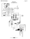
➄ Use the switch to move the traveling pan up and down. Removal of the
access panel will allow the observation of this movement. The unit will stop
automatically when it reaches the fully up or fully down po si tion.
➅ Cycle the unit in both directions until you are satisfi ed the unit is operating
properly. If for any reason the unit does not seem to op er ate properly, call
Draper, Inc. 765/987-7999. Do not pro ceed with installation.
➆ If the unit has been ordered with the remote control option, again verify
operation of the unit by use of the hand held transmitter. If for any reason
the unit does not seem to operate properly, call Draper, Inc., 765/987-7999.
Do not proceed with installation.
➇ If the unit is operating satisfactorily, remove and discard the tem po rary
plug.
➈ Disconnect the switch at the terminal board (terminals #1, #3, and #7). Do
not discard this switch. It is to be used as the wall switch.
➉
Replace the cover on the electrical box and proceed with the installation,
referring to instructions supplied.
Copyright © 2008 Draper Inc. Form LCDLift220V_Inst08 Printed in U.S.A.
A B C D Travel Lift
(cm) (cm) (cm) (cm) (cm) Capacity
LCD Lift A 60 45 46 28 29 30 kgs
LCD Lift B 73 57 58 41 42 30 kgs
Continued on next page
If you encounter diffi culties installing or servicing your LCD Lift, call
your dealer or Draper, Inc., Spiceland, Ind., (765) 987-7999; or fax
(765) 987-7142.