


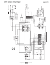

220V Scissor Lift by Draper page 3 of 6
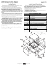
Installing Optional Ceiling Finish Kit
The Scissor Lift is available with a ceiling fi nish kit, which consists of the lower
section of the plenum housing (trim frame) and the closure panel.
➀ Install Scissor Lift as previously described in these instructions.
➁ Install trim frame in opening. This can be accomplished by suspending with
wire or mounting directly to ceiling joists (if space permits).
➂ Install projector and attach optional ceiling closure panel to Scissor Lift. See
above for appropriate ceiling closure instructions.
Ceiling Finish Kit
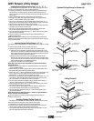
Installing Optional Ceiling Closure Panel—"B", "S", "E", "J"
If your Scissor Lift is equipped with a "B" or "E" ceiling closure panel, it can be
used as is, or in conjunction with a piece of existing ceiling tile.
➀ If installing with ceiling tile, you may need to cut tile so its overall dimensions
are the same as (or slightly less than) the closure panel. Place tile into trim
frame. Lay closure panel on top (back side) of ceiling tile, and tighten screws to
hold in place.
➁ Attach provided angle brackets to side of bottom pan of Scissor Lift.
➂ For larger units, attach short angle brackets to ends of long angle brackets.
➃ Attach
5
/
16
" (8mm) threaded rods to angle bracket.
➄ Run unit “up” until bottom pan stops at highest position. Mark po si tion on
5
/
16
"
(8mm) rods even with ceiling and cut to length (remove from pan if convenient).
➅ Run unit “down” until bottom pan stops at “show” position.
➆ Attach closure to lower end of
5
/
16
" (8mm) rods by slipping into four corner slots
and secure with nuts above and below slots.
➇ Run unit “up” again to highest position. Measure distance by which panel
fails to reach required “closed” height for sur round ing ceil ing.
➈ Run unit “down” then re-adjust mounting of
5
/
16
" (8mm) rods in traveling grid to
raise panel required distance.
➉ Test unit operation to confi rm that panel will stop in closed position just
before touching ceiling.
NOTE: Immediately upon completion of the surrounding ceiling, unit should be
operated to confi rm that optional ceiling closure panel stops just short of touching
ceiling in closed position.
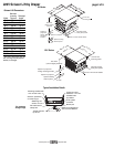
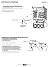
Optional Ceiling Closure for Scissor Lift
Installing Optional Ceiling Closure—"G", "U"
Your Scissor Lift can be equipped with an optional ceiling closure sys tem. To install
it:
➀ Remove closure and all mounting hardware from carton.
➁ Optional ceiling closure can be mounted in either of the following styles:
A. If ceiling tile is to be inserted in the closure, this may be done now, or later
when the rest of the ceiling is in stalled (per mit ting a better match). Cut tile so
that its overall dimensions are the same as (or slightly less than) the closure
panel. Attach to the closure panel with adhesive.
B. Position one pre-cut aluminum tee along outside edge of panel so arm
extends under and rests on the panel (or tile if tile is being used). Be careful
not to compress the tile. Drill three holes through rib of tee into edge of panel
and pop rivet into place (or use self-tapping screws).
C. Follow same procedure with remaining 3 tees.
NOTE: Since tees comprise part of exposed trim, care should be taken to
ensure accurate fi t.
➂ Attach two (2) mounting angles to the corresponding holes in the bottom pan
with the supplied hardware.
➃ Attach other two (2) mounting angles at 90° to previous angles (right to left) in
the corresponding holes with the supplied hard ware.
➄ Attach one of four
3
/
8
" (10 mm) threaded rods by passing the rod through one of
the four corner holes, in the angles and secure with nuts top and bottom.
Approximately ½" (13 mm) of rod should extend above angle.
➅ Run unit “up” until bottom pan stops at highest position. Mark po si tion on
3
/
8
" (10
mm) rod that is even with ceiling level and cut rod to length (removing it from
pan if convenient). Cut remaining three rods to same length.
➆ Run unit “down” until bottom pan stops at “show” position. Secure all four
3
/
8
"
(10 mm) rods to traveling pan in same fashion as fi rst one.
➇ Attach closure to lower end of each
3
/
8
" rod using two remaining nuts on each
rod to fi rmly clamp fi xtures on top of panel.
➈ Run unit “up” again to highest position. Measure distance by which panel
fails to reach required “closed” height for sur round ing ceil ing.
➉ Run unit “down” then readjust mounting of
3
/
8
" rods in traveling grid to raise
panel required distance.
NOTE: Rods should not extend more than 1" above the angles attached to
the pan. Cut extra rod off if necessary.
11
Test unit operation to confi rm that panel will stop in closed position just
before touching ceiling.
Threaded Rod
Trim Frame
Closure Pan
Installer to Drill Holes
Optional Acoustical
Tile by Others
Pop Rivets or Screws
Supplied by Others
Tee Moulding
(w/Mitred Corners)
8-32 Weld Studs
Angles with
Pre-drilled Holes
Bottom Pan of
Scissor Lift
Threaded Rod
Optional Acoustical
Tile by Others
Tee Moulding
(w/Mitred Corners)
Installer to Drill Holes
Closure Pan
E, G, J
Pop Rivets or Screws
Supplied by Others
Bottom Pan of
Scissor Lift
Angles with
Pre-drilled Holes
www.draperinc.com
(765) 987-799
9