


Copyright © 2008 Draper Inc. Form ScissorLift_220VInst08 Printed in U.S.A.
Caution:
➀ Read instructions completely before proceeding.
➁ Test lift prior to installation.
➂ Follow instructions carefully. Installation contrary to instructions
invalidates warranty.
➃ Do not obstruct operation of Scissor Lift with fi ngers or any object.
Serious injury or damage could result.
➄ Scissor Lift is designed to accommodate ceiling suspended equip ment.
Equipment should not be allowed to rest on optional ceiling closure
during operation. (Refer to section titled “Installing Pro jec tor.”)
➅ Entire bottom of unit must be unobstructed to permit proper op er a tion.
Suffi cient clearance must be allowed below projector or op tion al ceiling
closure: see chart on page 4.
➆ Unit must be installed level (use a carpenter’s level).
➇ Unit operates on 220V, 50 Hz. AC current.
Note: Unit has been thoroughly inspected and tested at factory and found
to be operating properly prior to shipment.
Planning
➀ Based on screen location and projector specifi cations, determine proper
position for projector in stal la tion.
➁ Confi rm that there is adequate space for installation and operation.
Minimum clear ance above ceiling level varies according to Scissor Lift
model, plus height of projector, optional mounting bracket, optional ceiling
closure, and optional plenum rated housing.
➂ Arrange to provide service access to the unit.
As Soon As Scissor Lift Arrives
➀ Open carton and inspect for damage.
➁ Locate the following parts:
A. The unit itself
B. Controls
C. Any optional equipment: plenum housing, closure panel, ceiling fi nish kit
or decorative cover (all ship in separate cartons).
➂ Test lift prior to installation.
Installation/Operating Instructions
220V SL & SLX Scissor Lift Video Projector Lift by Draper
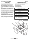
Hanging Unit
The Scissor Lift may be installed in a variety of ways; recessed above the
ceiling, or sus pend ed below the ceiling. The lift should be supported by four
½" thread ed mount ing rods. If ceiling recessed, the entire unit (including
the projector) should set approximately 1½" above the fi n ished ceiling in its
“stored” position. The threaded rods should pass through the corner mount ing
fl anges and be secured by nuts above and below. Use a thread locking
compound such as Loctite
®
#242 (provided). The unit should then be guy
wired or blocked to pre vent swing ing.
All installations should observe the following guidelines:
➀ Access from above the unit, with enough clearance to remove the top
cover, should be pro vid ed in case service is re quired. If installing above a
hard ceiling, optional Draper Access Panels are available to allow access to
the unit.
➁ Installer must ensure that all fasteners and supports are of ad e quate
strength to securely support Scissor Lift and projector.
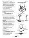
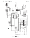
Electrical Connections
Unit operates on 220V AC, 50 Hz. current. Removing the top cover of the
unit and opening the electrical box ex poses ter mi nals for fi eld con nec tions.
Unit is shipped with internal wiring com plete. Wire to connect unit to power
supply should be furnished by in stall er. Con nec tions should be made in
accordance with wiring di a gram, and wiring should com ply with na tion al and
local elec tri cal codes. All op er at ing switches should be “off” before power is
con nect ed.
Scissor Lift should be operated and checked prior to installing pro jec tor and/or
optional ceiling closure.
Standard switch shown below comes with 22.86 meters of cable and should
be plugged in to box on front of top pan of lift to control lift.
®
Loctite
®
is a registered trademark of Henkel Corporation.
These Installation/Operating Instructions are available in the offi cial language
of the country where you purchase the product. Please contact your
distributor to request a copy.
Vous pourriez demander les instructions d’installation et d’opération traduises
dans la langue offi cielle du pays ou vous achetez le produit. Veuillez
demander à votre distributeur.
Die Gebrauchsanweisung für Installation und Konstruktion sind in der
offi ziellen Sprache des Landes, indem Sie das Produkt gekauft haben,
vorhanden. Fragen Sie die jeweilige Verkaufs-Abteilung.
If you encounter any diffi culties installing or servicing your Scissor Lift, call your
dealer or Draper, Inc. in Spiceland, In di ana, 765-987-7999; or fax 765-987-7142.
➂ Fastening methods must be suitable for mounting surface, and se cure ly
anchored so that vibration or abusive pulling on unit will not weaken
installation.
➃ Unit should be level, with weight shared more or less equally by all four
threaded mount ing rods.
➄ Bottom of unit must be unobstructed after installation. Suffi cient clear ance
must be allowed below projector or optional ceiling closure: 4' for Model
SL4, 5' for Model SL5, etc.; 11' for Model SLX11, 12' for Model SLX12, etc.
➅ Do not use unit to support adjacent ceiling, light fi xtures, etc.
➆ Do not complete the ceiling below unit until electrical connections have
been completed and unit has been operated successfully.
➇ We recommend that safety cables be attached to the Scissor Lift for added
security (a sound in stal la tion practice with overhead equipment).
Operation
When unit is fi rst operated, be cautious! If unit fails to operate when toggle
switch is fl ipped “down”, return switch to “off” and recheck elec tri cal
con nec tions before pro ceed ing. Cycle unit down and up several times to
confi rm sat is fac to ry operation.
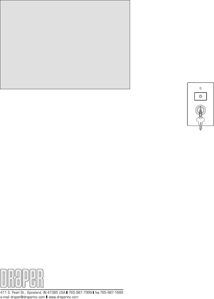
Standard Single Station Control (CE Approved)—One, 12V toggle switch:
mov ing 3-po si tion toggle switch to “down” po si tion will start lift down. Moving
toggle switch to “up” will start lift up. When lift is in “show” position, travel will
au to mat i cal ly be stopped by factory set limit switch es. When ev er switch is
placed in center “off” position, operation will stop. One, 12V key switch will
lower lift from “show” to “service” position.
Video Interface Control (CE Approved)—This optional 12V control device
allows the Scissor Lift switch to control the operation of a Draper motorized
pro jec tion screen via a relay.
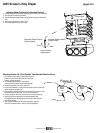
Multiple Station Control (Not CE Approved)—Optional, moves lift from
“stored” to “show” position only. Each switch ing station has a 3-button switch
with “up”, “down”, and “off” buttons. Lift starts up or down when ap pro pri ate
button is pressed, and may be stopped by pressing “off” button. Factory set
limit switch es stop lift automatically when pro jec tor is in “show” position.
Key Operated Switch (Not CE Approved)—If ordered, a single station, key-
operated three position (up/off/down) switch is available. Multiple Station Con-
trol re quired for this option. Moves lift from “stored” to “show” positions only.
Infrared or Radio Frequency Remote Control (CE Approved)—If ordered, a
three-button transmitter is provided, with “up”, “down”, and “stop” buttons. Unit
starts up or down when appropriate button is pressed, and may be stopped by
pressing “off” button. Factory set limit switches stop unit au to mat i cal ly when
projector is in “show” po si tion. Only controls "show" and "stored" positions.
UP
DOWN
OFF
OFF