


6
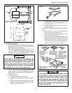
D. Wiring Requirements
1. 120 VAC Supply Line
Route a copper 12 AWG, with ground, 120 VAC
supply line from the time delay fuse or circuit breaker
box to the roof opening.
a. This supply line must be located in the front
portion of the 14-1/4" x 14-1/4" (±1/8") opening.
b. The power MUST be on a separate 20 Amp time
delay fuse or HACR circuit breaker.
c. Make sure that at least 15" of supply wire
extends into the roof opening. This ensures and
easy connection at the junction box.
d. Wiring must comply with all National, State and
Local Wiring Codes.
e. Use a steel sleeve and a grommet or equivalent
methods to protect the wire where it passes into
the opening.
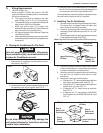
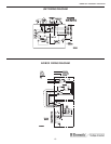
E. Placing Air Conditioner On The Roof
This unit weighs approximately 100 pounds.
To prevent back injury, use a mechanical hoist
to place Air Conditioner on roof.
FIG. 7
Do not slide the unit. This may damage the
roof gasket attached to the bottom and may
create a leaky installation.
CAUTION
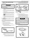
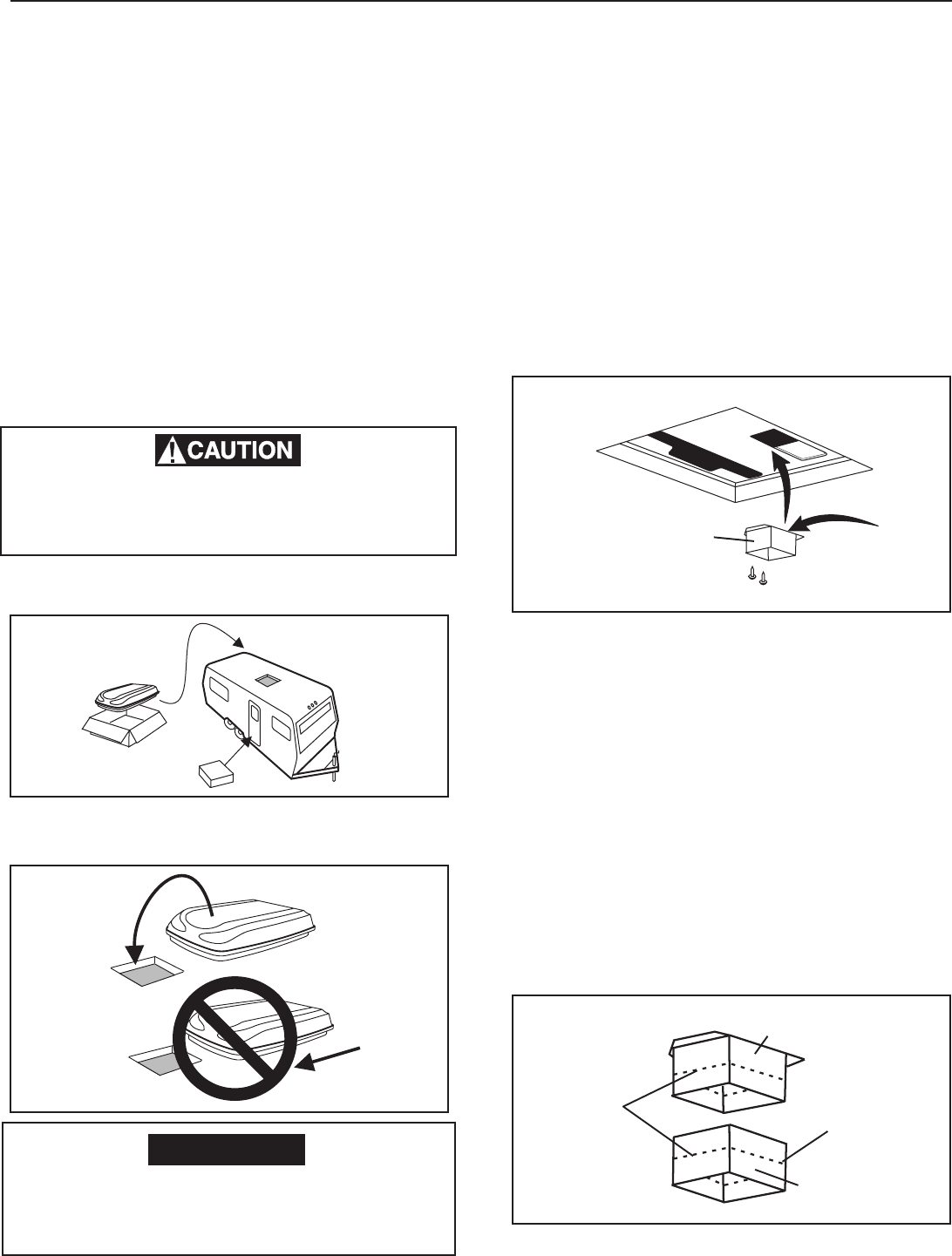
1. Remove the air conditioner from the carton and dis-
card carton. See FIG. 7.
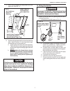
2. Place the air conditioner on the roof.
3. Lift and place the unit over the prepared opening using
the gasket on the unit as a guide. See FIG. 8.
4. Place the 3106152.006 Mechanical Air Distribution
Box Kit. This box contains mounting hardware for the
air conditioner and will be used inside the RV.
This completes the outside work. Minor adjustments can
be done from the inside of the RV if required.
F. Installing The Air Conditioner
1. Remove air box and mounting hardware from carton.
The upper duct is shipped inside the lower duct
which is part of the ceiling template.
2. Check for correct alignment and adjust the unit as
necessary (Roof Gasket centers over 14-1/4" ±1/8"
opening).
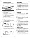
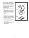
3. Remove upper duct from ceiling template and locate
it over blower discharge. See FIG.9.
Note: Edge without flange installs toward REAR of opening.
FIG. 8
FRONT
FIG. 10
Step a
Remove At
Perforation
Step b
Remove At
Perforation
Step c
Use As
Packaged
Upper Discharge
Air Duct
Lower Discharge
Air Duct
Rear Of Air
Conditioner
Upper Discharge
Air Duct
Edge Without
Flange To
Rear Of Unit
FIG. 9
4. Use two (2) sharp pointed #10 sheet metal screws
to hold duct to base pan. Screw holes are provided
in bottom of base pan for these screws.
5. Reach up into return air opening of the air conditioner
and pull the unit electrical cord down for later
connection.
6. Measure the ceiling to roof thickness:
a. If distance is 1"-2", remove perforated tabs from
both upper and lower ducts. See FIG. 10.
b. If distance is 2"-3", remove perforated tabs from
bottom duct only. See FIG. 10.
c. If distance is 3"-4", install ducts as received.
See FIG. 10.
d. If distance is 4"-6", use optional 318556.000
Duct Adaptor and 3100895.006 Bolt Kit. See
FIG. 10.
630025.331 Installation Instructions