


15
TROUBLESHOOTING GUIDE (cont’d)
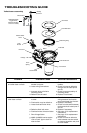
Replacing the flush ball seal and bowl seal
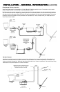
1. Turn off water and electrical power to toilet.
2. Remove water inlet hose from toilet.
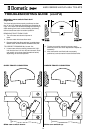
3. Remove toilet from oor and turn it upside down.
Disconnect Service Switch wires at
in-line connectors.
4. Remove three nuts and at washers securing base
assembly to toilet bowl using a 1/4-inch drive ratchet
wrench, 7/16-inch deep-well socket and extension.
5. Pull check valve out of the sealing grommet located
in rear of toilet bowl.
6. Lift base assembly from toilet.
7. Replace old seals with a complete seal kit.
8. Reconnect base assembly to toilet with new
mounting bolts (L-shaped) included with seal kit.
Tighten nuts to 20-25 in.-lbs. torque.
9. Reconnect Service Switch wires. Reattach water
inlet hose to toilet.
10. Reinstall toilet to oor.
Replacing the flush ball
1. Turn off water to toilet.
2. Open ush ball in Service Mode, then turn off power
to toilet.
3. Disconnect water inlet hose.
4. Remove toilet from oor and turn upside down,
and disconnect Service Switch wires at in-line
connectors.
5. Pull check valve out of sealing grommet located in
rear of toilet bowl.
6. Remove three nuts and at washers securing base
assembly to ceramic toilet bowl using a 1/4-inch
drive ratchet wrench, 7/16-inch deep-well socket
and extension.
7. Lift base assembly from toilet.
8. Remove bowl seal, ush ball seal, and retainer plate
to expose ush ball.
9. Loosen set screw in the rotor shaft cam using
a 1/8-inch hex tool.
10. Remove the #8 x 1/4-inch long screw and at washer
from linkage slot.
11. Remove the four screws securing the mounting
bracket to base.
12. Pull mounting bracket and rotor cam off base.
13. Rotate ush ball forward and remove ush ball
retaining screw.
14. Replace ush ball and reverse disassembly through
step 10.
15. Push rotor cam all the way onto rotor shaft. Tighten
set screw.
16. Lubricate moving parts with silicone grease.
17. Before reassembling entire toilet, the cam switch
may require adjustment. See “Adjusting The Cam
Switch” on page 14.
Replacing the rotor shaft
1. Follow disassembly steps 1 through 14 under
“Replacing the Flush Ball”.
2. Pull rotor shaft out from inside of the base.
3. Lubricate O-rings on new shaft with silicone grease.
4. Align at section on rotor shaft with at section in
cam during assembly. Push rotor shaft cam fully
onto rotor shaft. Tighten set screw.
5. Lubricate moving parts with silicone grease.
6. Reverse the disassembly procedure.
7. Before attaching base to toilet, the cam
switch may require adjustment. See
“Adjusting The Cam Switch” on page 14.
Replacing the rotor shaft cam
1. Follow disassembly steps 1 through 14 under
“Replacing the Flush Ball”.
2. Remove linkage pin clip and pin.
3. Attach new rotor shaft cam to linkage using
pin and clip.
4. Lubricate moving parts with silicone grease.
5. Reverse the disassembly procedure.
6. Before attaching base to toilet, the cam
switch may require adjustment. See
“Adjusting The Cam Switch” on page 14.
Replacing the motor drive arm
1. Follow disassembly steps 1 through 11 under
“Replacing the Flush Ball”.
2. Remove the four motor mounting screws.
3. Remove the motor from the mounting bracket.
4. Loosen the Drive Arm set screw using a 3/32-inch
hex tool, then remove old Drive Arm.
5. Install new Drive Arm and push onto motor shaft as
far as possible. Tighten the set screw.
6. Lubricate moving parts with silicone grease.
7. Reverse disassembly procedure.
8. Before attaching base to toilet, the cam
switch may require adjustment. See
“Adjusting The Cam Switch” on page 14.
Replacing the drive linkage
1. Follow disassembly steps 1 through 13 under
“Replacing The Flush Ball”.
2. Remove linkage pin clip and pin at rotor shaft cam.
3. Remove the ush spring retaining screw and washer
from the retaining post.
4. Remove the ush spring from the old linkage.
5. Insert the ush spring into the new linkage
and reattach the spring to the retaining post.
6. Attach linkage to rotor shaft cam using pin
and clip.
7. Lubricate moving parts with silicone grease.
8. Reverse the disassembly procedure.