


5
INSTALLATION INSTRUCTIONS
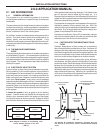
2.1.5 AIR FLOW AND FRICTION
Air flows in a duct system from a region of high pressure to
a region of lower pressure. The blower creates the pressure
differential which causes the air flow through the duct
system. The point of highest pressure in the system is at the
outlet of the blower. The point of lowest pressure in the
system is at the return opening of the blower. The air pressure
constantly decreases as the air flows through the system.
The pressure ultimately diminishes to zero as it passes
through the register and is diffused into the conditioned
space. As air moves through a duct, a pressure drop occurs
due to the friction between the air and the walls of the duct.
Another factor in pressure drop is the turbulence within the
air stream itself. Air moving within a duct does not flow in a
placid stream. Rather it moves in a churning and mixing path,
or “turbulent flow.” The cumulative effect of rubbing friction
and turbulence friction is friction loss. Air turbulence in a duct
system becomes substantial whenever there is a change in
the direction of air flow.
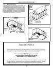
2.1.6 ECONOMICS OF DUCT DESIGN
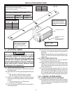
In order to match to the system air delivery capacity, elbows
for turning the air must be kept as large as allowed by the unit
construction. Duct depth for Dometic air conditioners
may vary with each model series. Confirm the system
to be installed and refer to Figure 3.4, for specific duct
configurations required. High loss elbows must have their
resistance lowered by the use of splitters or turning vanes.
Refer to Figure 2.3 through 2.7.
Another factor in duct losses is air leakage. Although
leakage is not considered in duct design it should be an
installation consideration. Cold air leaking into the surround-
ing cavity will cause condensation to form under high
humidity conditions. Sealing all joints will assure moisture
free cavities and maximum distribution of air to the outlets.
In most cases of high resistance encountered in duct
systems, one or more of the following points have been
overlooked by the installer:
A. Small Diameter
Pressure losses increase as diameter of a duct is
reduced. Good design practice is that which enables the
installer to put in the smallest size duct that will do the
job of delivering required airflow rate with pressure
available. No single size of duct will prove to be ideal for
all jobs.
B. Length of Duct
Pressure loss increases as duct length is increased.
This is almost obvious; a duct which is 6 ft. long has twice
the pressure loss of one that is 3 ft. long, provided that
both ducts are the same size and both are carrying the
same airflow rate.
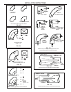
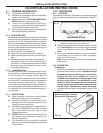
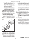
C. Changes in Direction (Figure 2.7)
Pressure losses increase when direction of air flow is
changed. When air is forced to make a 90° turn in a duct
system, pressure loss is much greater than for a straight
run of the same length. (Refer to FIG. 2.7)
Item 1. This sharp-angled bend causes a large pressure
loss. A simple way of visualizing such pressure loss is
to imagine that these diagrams represent highways on
which you are driving a car. As you approach a bend you
are forced to slow the car speed to 15 mph. In so doing,
a considerable part of energy of the fast-moving car has
had to be absorbed by the brakes. The analogy holds for
air particles flowing around a sharp bend.
Item 2. This sharp-angled bend on the inside corner
causes great pressure loss. The rounded corner on the
outside does not help as much as might be anticipated.
Item 3. This is a common form of 90° bend that has
relatively low resistance.
Item 4. If minimum resistance is desired, this extreme
example of a smooth, streamlined fitting can be used,
although space requirements will be prohibitive in many
installations.
Item 5. Occasionally, a beam or rafter prevents the use
of a smooth bend and a right angle bend is necessary.
In such cases the use of turning vanes (splitters) will be
effective in reducing resistance.
Item 6. Another way to reduce resistance is to change
item (3) to a modified version of item (4) by inserting
splitters in the sharper bend.
D. Sudden Contraction
When air is suddenly contracted from a large duct to a
small duct, a pressure loss occurs See Figure 2.8.
E. Sudden Expansions
The pressure loss resulting from the sudden expansion
of air from a small duct to a large duct, are much larger
than losses due to sudden contraction. As with sudden
contraction, much can be done by making air expansion
gradual, rather than abrupt. See Figure 2.9.
To summarize Section 2.1.6, the following items contrib-
ute to higher pressure losses in a duct system:
1. Smaller diameter ducts
2. Longer duct lengths
3. Changes in direction of air flow