


2
TABLE OF CONTENTS
About your new thermostat
Features .....................................................................................................................2
System Conguration & Initialization ..........................................................................2
Factory preset settings ...............................................................................................3
Quick reference to control buttons..............................................................................3
Quick reference to LCD icons.....................................................................................3
Programming & Operations
ON/OFF ......................................................................................................................3
Clock setting ...............................................................................................................4
Temperature format ºF/ºC ...........................................................................................4
Inside Temperature .....................................................................................................4
Outside Temperature ..................................................................................................4
Zone Selection............................................................................................................5
Mode Selection ...........................................................................................................5
Fan Speed ..................................................................................................................5
Temperature Set-Point................................................................................................5
Dehumidify Setting (Select Models) ...........................................................................6
Mode description
OFF ............................................................................................................................6
Cool ............................................................................................................................6
Heat Pump..................................................................................................................6
Heat Strip....................................................................................................................7
Fan ............................................................................................................................7
Furnace/Aqua .............................................................................................................7
Auto Change Over ......................................................................................................7
Special Features
Auto Fan .....................................................................................................................8
Zone Control ...............................................................................................................8
Dehumidify (Select Models)........................................................................................8
Program 1 & 2 ............................................................................................................8
CANbus ......................................................................................................................9
Auxiliary Heat (Heat Pump Models Only) ...................................................................9
Stage Select (Two Air Conditioners/Heat Pump Units)...............................................9
Stage Select (Models Equipped With Two Compressor) ............................................9
Automatic Generator Start ..........................................................................................10
Load Shed ..................................................................................................................10
Defrost Cycle (Heat Pump Models Only)....................................................................10
Compressor Time Delay .............................................................................................10
Power Interruption ......................................................................................................10
LCD Error Codes ........................................................................................................10
System Reset Procedure .........................................................................................11
General Information .................................................................................................12
Maintenance ..............................................................................................................12
Service .......................................................................................................................12
Congratulations! Your recreational vehicle manufacturer has equipped your RV with
the most advanced RV thermostat. Your Dometic Comfort Control Center 2 thermo-
stat (hereinafter referred to as the CCC 2 thermostat) has been designed for ease of
operation and for many years of reliable service.
Features
• Liquid Crystal Display
• 2 operation programs
• Outdoor temperature sensing (select models)
• Constant time of day display
• Remote Sensor (Precise comfort control within 1º F. of set-point)
• Display reminder lets you know when to service or replace lters
• Up to 4 independent zones
To help familiarize yourself with the operation of the CCC 2 thermostat, review the
following diagrams and accompanying text that explain the functional characteristics
of this system.
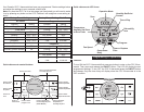
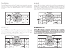
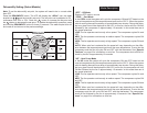
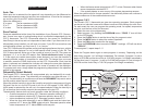
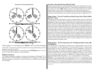
Your CCC 2 thermostat is equipped with a liquid crystal display (LCD) that identies
the mode of operation (OFF, Cool, Heat Pump, Fan, Heat Strip, Auto, & Furnace or
Aqua), temperature set-point, zone identication (1, 2, 3, 4), fan speed (Auto, Low,
Med, High), program 1 and 2, inside temperature, outside temperature, clock, ºF/ºC,
compressor delay, lter maintenance, and dehumidify operation with humidity set
point. The modes of operation viewed in the LCD will vary depending on the system
installed in your RV.
System Conguration & Initialization
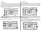
The installer of your system will set the required system DIP switches to the ON
position. In order for the CCC 2 thermostat to recognize the system zones, type of
units installed and their options, a system reset must be done. Once the system is
completely installed, do a system reset.
• Make sure the CCC 2 thermostat is in the OFF condition. See page 3, Quick
reference to control buttons.
• Simultaneously press and hold the MODE and ZONE buttons. See page 3,
Quick reference to control buttons.
• The LCD will display “IniT” and all available zones.
• Release the MODE and ZONE buttons.
• Press the ON/OFF button to exit system set up.
The furnace ON/OFF temperature differential should be set at this time. See “Pro-
gramming & Operations” on page 7 for further information on furnace mode dif-
ferential setting.
Any time a system reset occurs, the factory default settings are restored. See “Fac-
tory Preset Settings” on page 3.
In the unlikely event of CCC 2 system memory loss or dip switch setting change,
the CCC 2 thermostat will require a system reset. Refer to page 11 for system reset
procedure.
About your new thermostat