


5-2
5.2 Rear Panel Level Controls
Each analog output connector has a level control adjacent to it. Each analog output
is adjustable (at full scale) over a range of below 0dBu to greater than +24dBu.
5.3 Test Tone Level
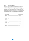
The operating level for the test tone generator of the Model DP524 is -18dB
relative to full scale. This is useful when calibrating the analog outputs and also for
checking proper operation of the digital outputs.
The actual frequency of the tone is dependent upon sample rate (see section 3.5.1).
5.4 Software Downloading Procedure
In the event that a software upgrade is required, the RS-232 (J105) may be used to
download the appropriate files and reprogram the EEPROM residing in the DP524.
When this method of upgrade is desired, the necessary files will be supplied in IBM
PC compatible format. The downloading procedure is described below.
Remove all connectors to the DP524 except for the mains power.
Connect rear panel connector J105 to a standard PC serial port.
Note the position of S101-5 and S101-6. They must be restored to this
position when the software downloading is complete.
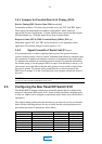
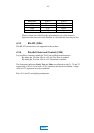
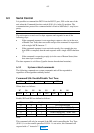
Set the baud rate select switches S101-5 and S101-6 as desired, according
to the table below:
Baud Rate S101-5 S101-6
9600 Down Down
19200 Down Up
38400 Up Down
Set rear panel switch S101-2 to the up position. As soon as this is done the
Front panel LEDs Mute, 48k, 44.1k and 32k will all be illuminated. During
the download sequence the Test LED will flash.
Software upgrades are supplied by Dolby Laboratories and include complete
instructions relating to the download procedure.
After the unit has been upgraded, move switch S101-2 back to its down
position. The unit will then reboot and begin running the new code.
Return switches S101-5 and S101-6 to their original positions.
MAIN